
Abutting joint device of steel lattice column, and construction method of same

A technology of steel lattice column and docking installation, which is applied in basic structure engineering, excavation, building construction, etc. And the effect of construction quality, easy construction operation and cost reduction

Active Publication Date: 2012-06-13
北京城建中南土木工程集团有限公司
View PDF8 Cites 21 Cited by
  • Summary
  • Abstract
  • Description
  • Claims
  • Application Information

AI Technical Summary

Problems solved by technology

[0003] The purpose of the present invention is to provide a steel lattice column butt joint installation device and construction method to solve the problem of material waste caused by the direct lengthening of the steel lattice column and is not conducive to the quality control of the steel lattice column positioning construction

Method used


Image

  • Abutting joint device of steel lattice column, and construction method of same
  • Abutting joint device of steel lattice column, and construction method of same
  • Abutting joint device of steel lattice column, and construction method of same

Examples


Embodiment Construction

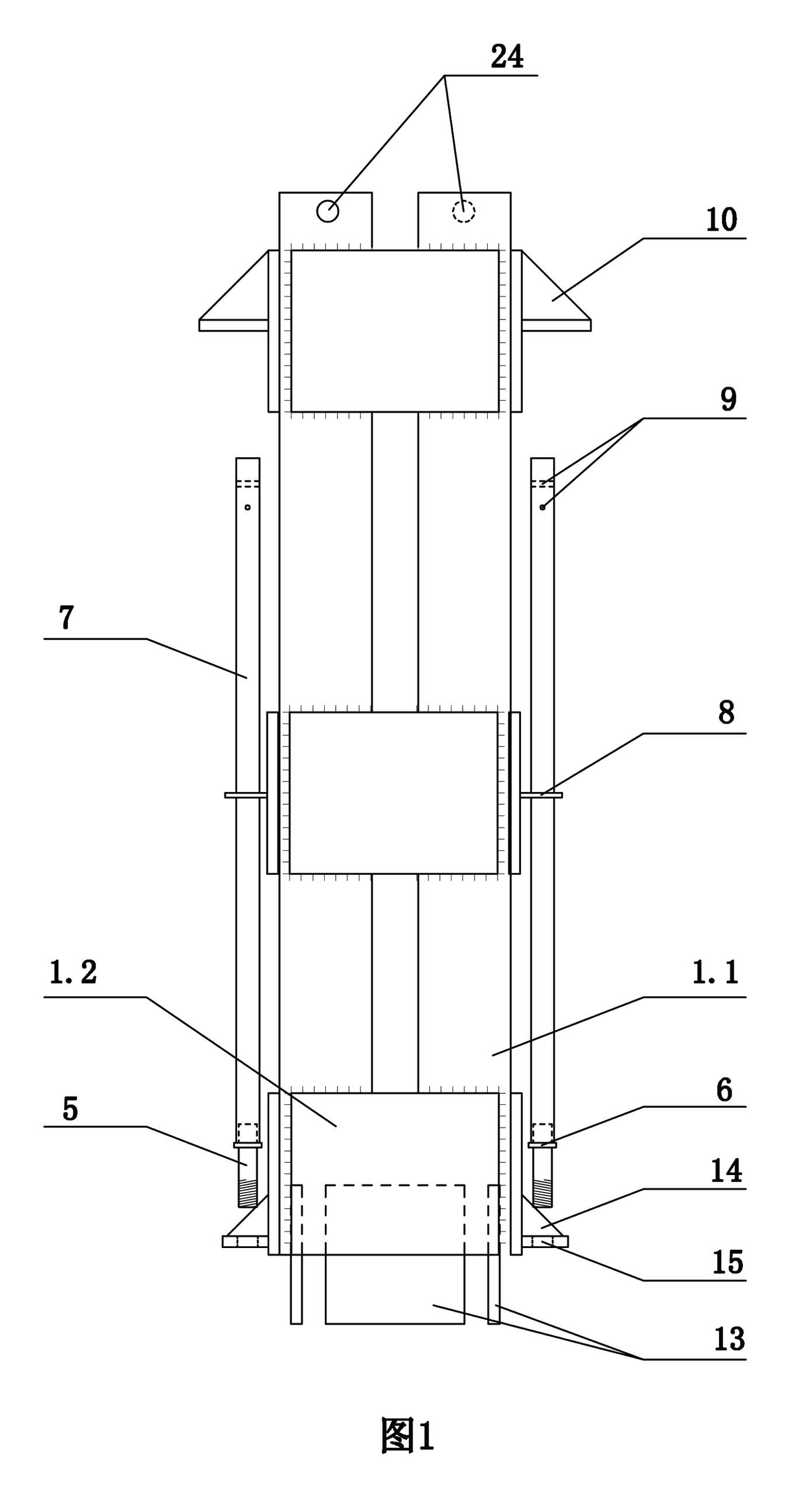
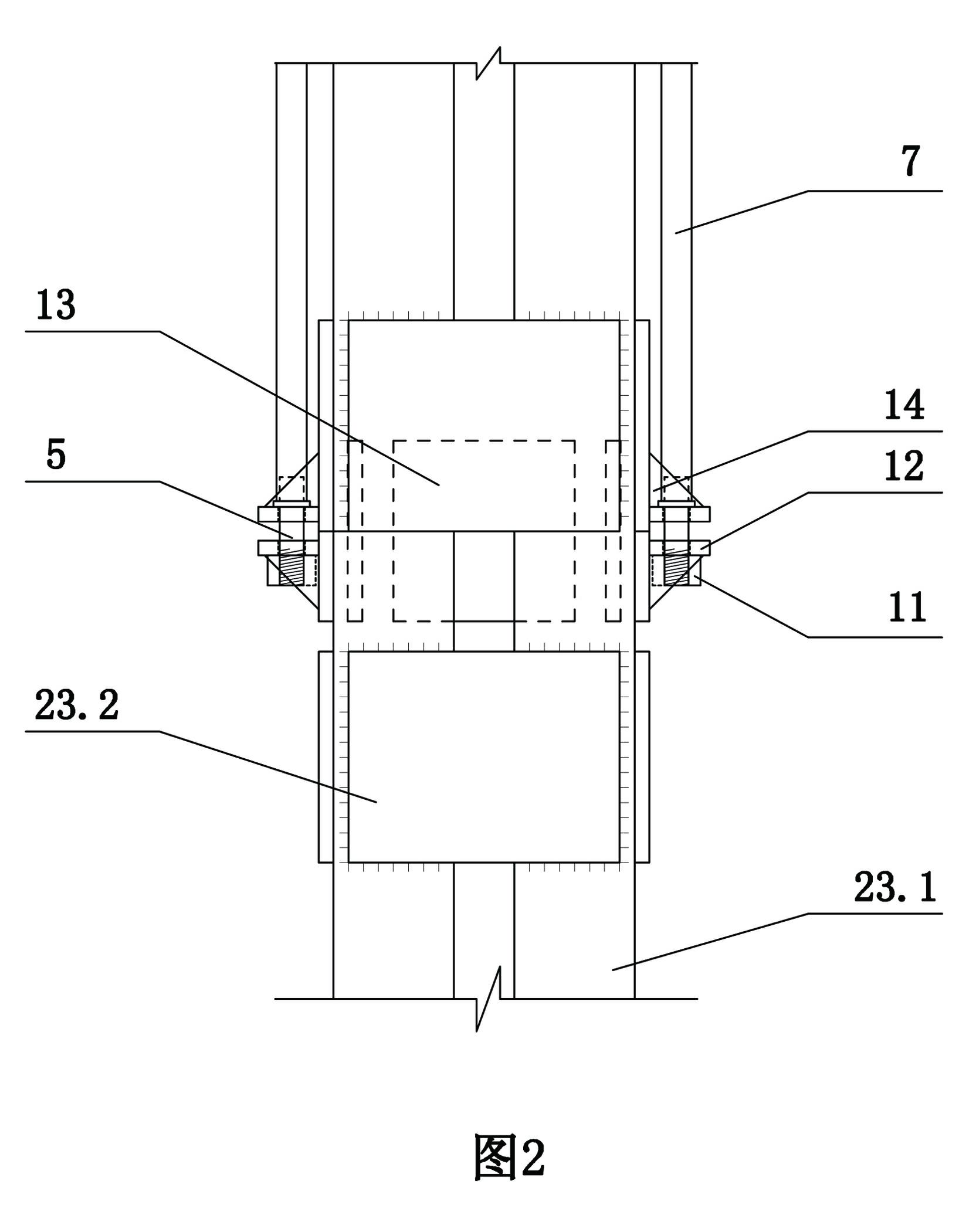
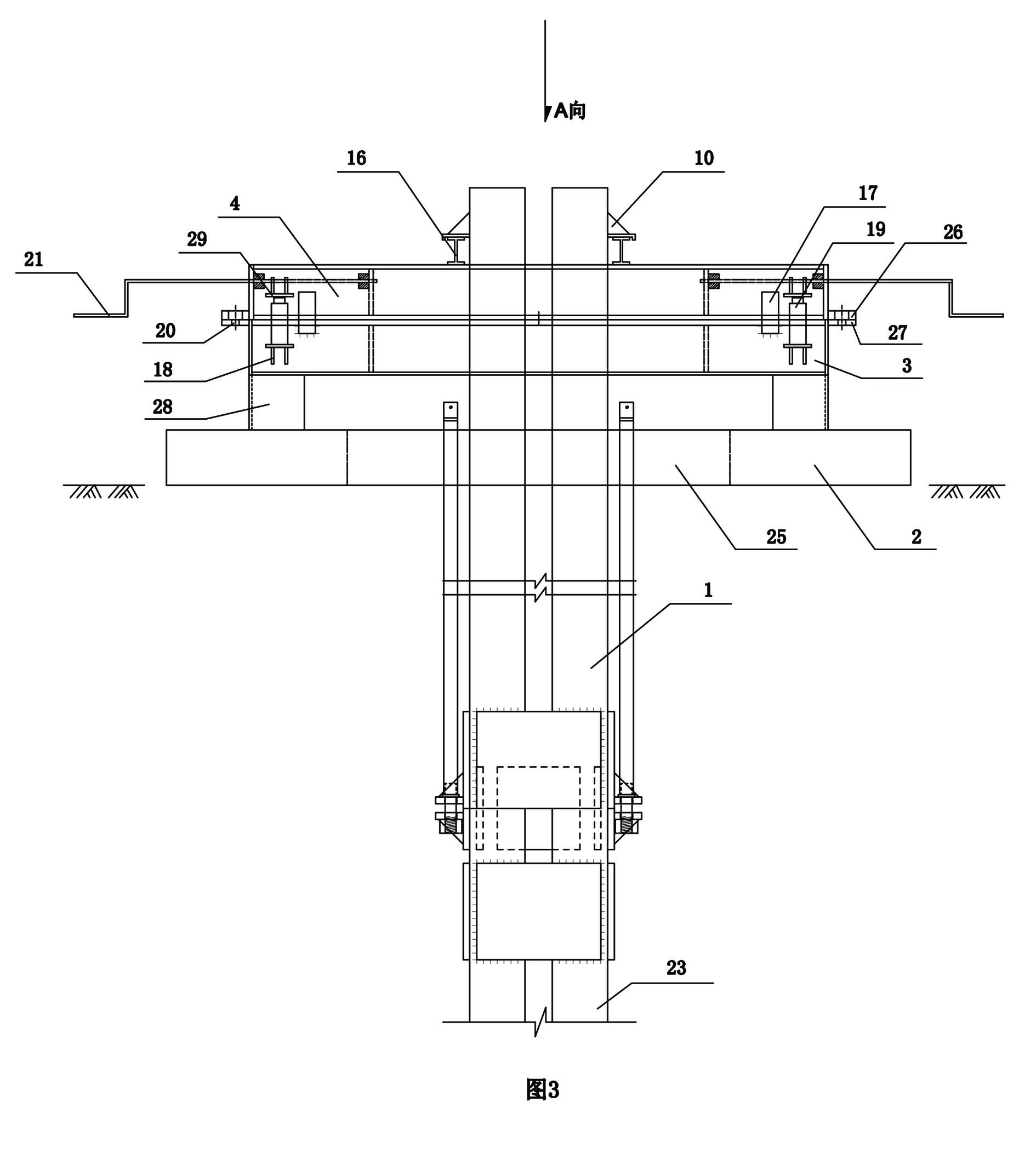
[0040] Examples see Figure 1-4 as shown,

[0041] A butt joint installation device for a steel lattice column, comprising a steel lattice column 23 composed of four angle steel limbs 23.1 and decorative plates 23.2 welded around the four angle steel limbs at intervals, the steel lattice column 23 The upper end of the joint 1 is connected with the joint 1, and the upper end of the joint 1 is connected with the locator;

[0042] Two limit corbels 12 are welded on the uppermost panels on the left and right sides of the steel lattice column 23, each limit corbel has a perforation, and a nut 11 is welded below the perforation.

[0043] The movable joint 1 is connected as a rigid body by four shaped steel columns 1.1 and surrounding steel parts 1.2 welded at intervals around the four shaped steel columns. The left and right sides of the rigid body are symmetrical structures, and the surrounding steel parts on the left and right A row of stirrup rings 8 are welded on the top, tw...


PUM


Abstract

The invention discloses an abutting joint device of a steel lattice column, which comprises the steel lattice column, wherein the steel lattice column is composed of four angle steel arm members and batten plates which are surrounded and welded around the four angle steel arm members at intervals; the upper end of the steel lattice column is connected with a movable joint; the upper end of the movable joint is connected with a locator; the movable joint is connected as a rigid main body by four section steel columns and steel surrounding members which are welded around the four section steel columns at intervals; the left side surface and the right side surface of the rigid main body are symmetrical structures; the movable joint is connected with the steel lattice column through an abutting joint screw rod; the locator is composed of a base plate, an adjusting frame support and an adjusting frame; the base plate is a cast-in-place reinforced concrete plate with middle holes; the adjusting frame support is a square-shaped hollow frame with four support legs; the hollow frame is internally filled with concretes; the adjusting frame is a square-shaped hollow frame obtained by welding steel plates and is arranged on the adjusting frame support; and the size of the adjusting frame is the same as that of the adjusting frame support. The abutting joint device of the steel lattice column, and the construction method of the same disclosed by the invention solve the problems in material waste and control of location and construction qualities if the steel lattice column is lengthened directly.

Description

technical field [0001] The invention relates to a steel lattice column positioning installation device and a construction method. Background technique [0002] With the continuous development and application of construction science and technology, in order to meet the purpose of speeding up the construction progress and reducing the project cost, the reverse method construction has been applied more and more. In the construction of the underground building structure using the reverse method, the underground main structure and the foundation pit The enclosure system is combined. Before the formation of the column-slab system in the structure, the steel lattice column should be used as the vertical support. At the same time, the steel lattice column can also be used as the vertical support of the inner support in the foundation pit enclosure system. Therefore, for the steel lattice The verticality, horizontal position, rotation angle and elevation control precision of the col...

Claims


Application Information

Patent Timeline
IPC IPC(8): E04B1/58E02D5/36E02D17/04
Inventor 马金华于海亮李玲高志刚娄志会李兴正黄锡阳
Owner 北京城建中南土木工程集团有限公司
Learn More