Timing positioning system device for top-mounted engine of camshaft

A positioning system and camshaft technology, applied in the direction of engine components, machines/engines, valve devices, etc., can solve the problems of accuracy and unsatisfactory assembly efficiency, achieve timely oil supply, simplify assembly process, and improve production efficiency Effect

Inactive Publication Date: 2012-06-13
DONGFENG CHAOYANG DIESEL ENGINE
View PDF4 Cites 6 Cited by
  • Summary
  • Abstract
  • Description
  • Claims
  • Application Information

AI Technical Summary

Problems solved by technology

The accuracy and assembly efficiency of this method ca

Method used


Image

  • Timing positioning system device for top-mounted engine of camshaft
  • Timing positioning system device for top-mounted engine of camshaft
  • Timing positioning system device for top-mounted engine of camshaft

Examples


Embodiment Construction

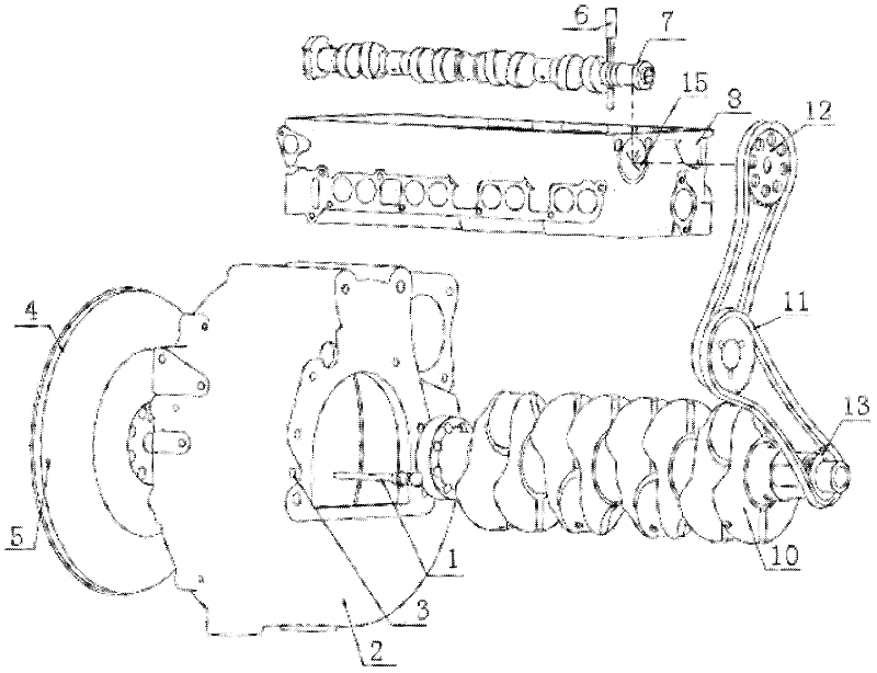
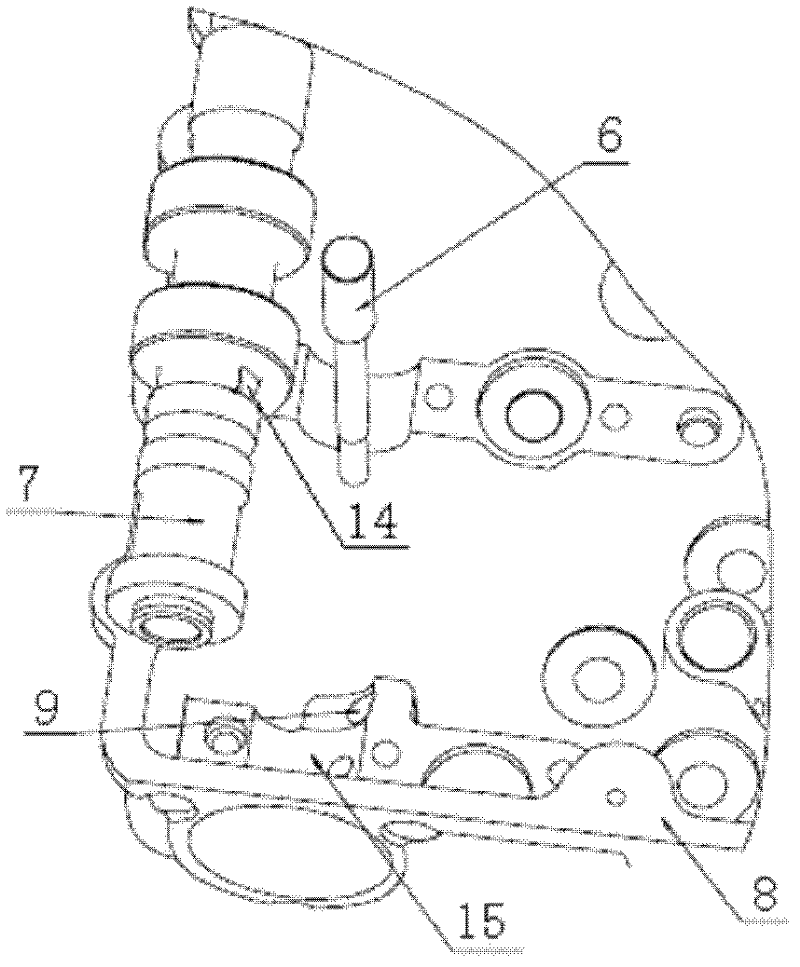
[0009] The structure of the present invention will be further described below in conjunction with the accompanying drawings. The timing positioning system device of the camshaft overhead engine, its component connection structure is as follows: the crankshaft positioning rod 1 passes through the positioning hole 3 on the flywheel housing 2 and inserts into the positioning pin hole 5 in the flywheel 4; the camshaft positioning pin 6 passes through The camshaft 7 is inserted into the cylinder head positioning hole 9 of the cylinder head 8 . The crankshaft gear disc 13 in the sprocket train is assembled with the crankshaft 10; the camshaft gear disc 12 in the sprocket train is assembled with the camshaft 7, and the camshaft 7 is assembled in the cylinder head cam positioning hole 15 (such as figure 1 ). The oil pump gear plate 11 in the sprocket train is assembled with the camshaft oil pump. The flat part of the camshaft positioning pin 6 is combined with the positioning surfac...


PUM


Abstract

The invention discloses a timing positioning system device for a top-mounted engine of a camshaft, which is structurally characterized in that a crankshaft positioning rod penetrates through a positioning hole on a flywheel shell to be inserted in a positioning pin hole in a flywheel; and a camshaft positioning pin penetrates through the camshaft to be inserted in a cylinder cover positioning hole of a cylinder cover, transmission relation between the camshaft and a crankshaft is determined, and timing positioning during gas distribution of the engine and timing positioning of oil supply are completed. A crankshaft gear disc in a chain wheel system is assembled with the crankshaft; a camshaft gear disc is assembled with the camshaft; and an oil pump gear disc is assembled with a camshaft oil pump. A planar portion of the camshaft positioning pin is assembled with a positioning surface of the camshaft in a combined manner, and the purpose of limiting rotation of the camshaft is realized. The accurate timing positioning system is provided by the aid of the top-mounted camshaft and chain transmission, so that gas distribution of the engine and oil supply can be timely and accurate. Components match with the corresponding positioning holes, the step that meshing marks need to be aligned in conventional assembly is omitted, assembly process is simplified, and production efficiency is improved.

Description

technical field [0001] The invention belongs to the structure of an internal combustion engine, and in particular relates to a chain drive timing positioning system device for a camshaft overhead engine. Background technique [0002] With the rapid development of internal combustion engine technology, people have higher and higher requirements for engine power, economy, emission and noise. With the adoption of many new technologies such as electronically controlled fuel injection, high-pressure distribution pump, and overhead cam , the requirements for the manufacturability of engine assembly and the processing level of parts are getting higher and higher. Among them, the accuracy of engine timing positioning is one of the main indicators reflecting engine performance. Its main function is to control the opening and closing of intake and exhaust valves through valve timing according to fuel injection time and fuel injection volume. At present, it is mostly used on the shock...

Claims


Application Information

Patent Timeline
IPC IPC(8): F01L1/348
Inventor 贺兆欣曹晓峰赵霄鹏逯明孙超陈军磊杨明李晓刚汪武强董立明周杰蔡云富
Owner DONGFENG CHAOYANG DIESEL ENGINE
Why Eureka
Try Eureka