
Multifunctional C4F7N/CO2 mixed gas distribution system and method

A C4F7N, mixed gas technology, used in mixing methods, gas and gas/vapor mixing, organic gas insulators, etc., can solve the problems of slow vaporization, unable to quickly prepare mixed gas, etc., to ensure stability and improve gas distribution rate. Effect

Pending Publication Date: 2019-10-11
ELECTRIC POWER RES INST OF STATE GRID ANHUI ELECTRIC POWER +2
View PDF13 Cites 4 Cited by
  • Summary
  • Abstract
  • Description
  • Claims
  • Application Information

AI Technical Summary

Problems solved by technology

[0007] What the present invention is to solve is because C 4 f 7 The N vaporization rate is too slow, which limits the C 4 f 7 N / CO 2 The technical problem that the mixed gas preparation speed cannot quickly prepare a large amount of mixed gas

Method used


Image

  • Multifunctional C4F7N/CO2 mixed gas distribution system and method
  • Multifunctional C4F7N/CO2 mixed gas distribution system and method
  • Multifunctional C4F7N/CO2 mixed gas distribution system and method

Examples


Embodiment 1

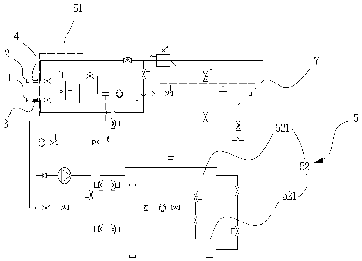
[0064] Such as figure 1 As shown, this embodiment discloses a multifunctional C 4 F 7 N / CO 2 Mixed gas distribution system, including C 4 F 7 N input port 1, CO 2 Input port 2, C 4 F 7 N heat exchanger 3, CO 2 Heat exchanger 4, C 4 F 7 N / CO 2 Mixed pipeline structure 5, C 4 F 7 N / CO 2 Mixed gas output pipeline structure 7.

[0065] C 4 F 7 N heat exchanger 3 is used to align the warp C 4 F 7 N input port 1 input C 4 F 7 N is heated and vaporized. CO 2 Heat exchanger 4 is used to compare CO 2 CO input from input 2 2 Perform heating and vaporization. C 4 F 7 N / CO 2 Mixing pipeline structure 5 is used to control the vaporized C 4 F 7 N, CO 2 To mix, C 4 F 7 N / CO 2 The mixed gas output pipeline structure 7 is used to output the mixed C 4 F 7 N / CO 2 mixed composition.

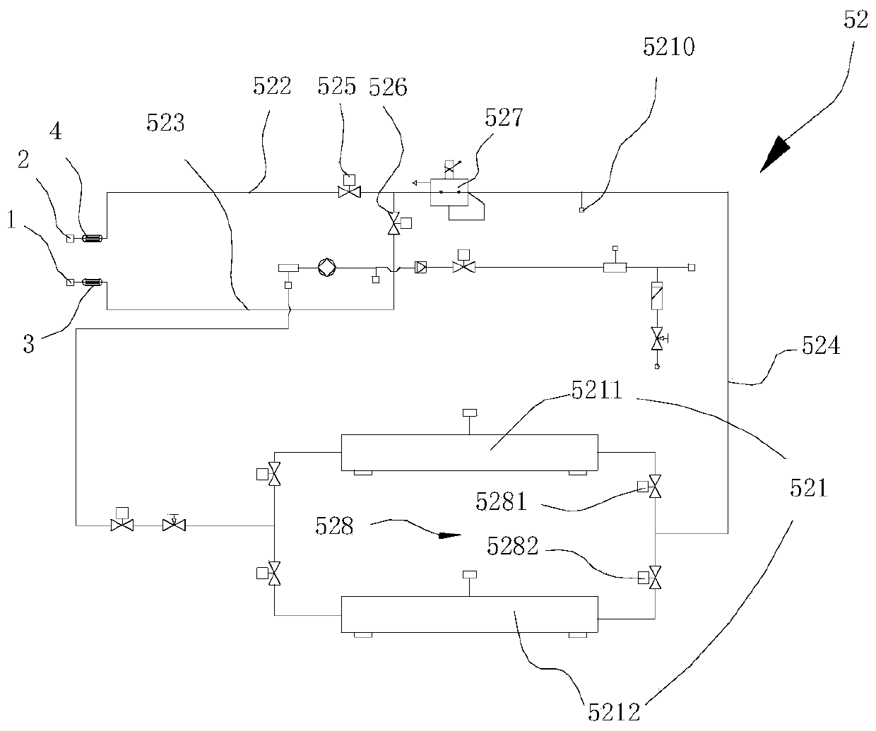
[0066] C 4 F 7 N / CO 2 Hybrid pipeline structure 5 includes C 4 F 7 N / CO 2 Dynamic gas distribution pipeline structure 51, C 4 F 7 N / CO 2 Partial pressure mixing pipeline structure 52.

[0067] C 4 F 7 N / CO 2 Dynamic gas d...

Embodiment 2

[0073] Such as figure 2 As shown, the difference between this embodiment and the above embodiment is that a specific C 4 F 7 N / CO 2 Dynamic gas distribution pipeline structure 51.

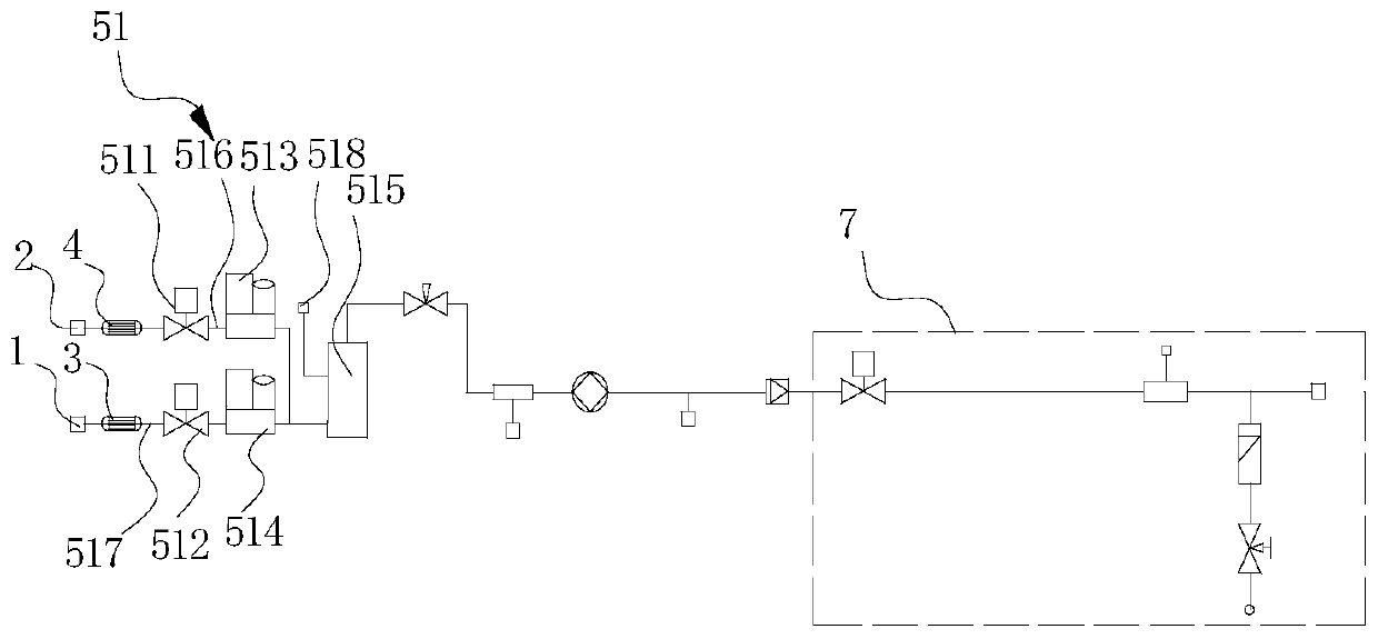
[0074] The C 4 F 7 N / CO 2 The dynamic gas distribution pipeline structure 51 includes a first solenoid valve 511, a second solenoid valve 512, a first thermal mass flow meter 513, a second thermal mass flow meter 514, a buffer mixing tank 515, a first pipe 516, and a second pipe 517.

[0075] The buffer mixing tank 515 is provided with a first air inlet, a second air inlet, and a first mixed gas outlet.

[0076] CO 2 The air outlet of the heat exchanger 4 communicates with the first air inlet through a first pipe 516, and the first solenoid valve 511 and the first thermal mass flow meter 513 are both arranged on the first pipe 516. C 4 F 7 The air outlet of the N heat exchanger 3 communicates with the second air inlet through a second pipe 517, and the second solenoid valve 512 and the second thermal ma...

Embodiment 3

[0080] Such as figure 2 As shown, the difference between this embodiment and the foregoing embodiment is that a first differential pressure sensor 518 is provided on the buffer mixing tank 515. By setting the first differential pressure sensor 518 on the buffer mixing tank 515, the mixed C 4 F 7 N / CO 2 The pressure of the mixed gas is tested to further monitor the accuracy of the mixed gas. Of course, if C 4 F 7 N / CO 2 The pressure value of the mixed gas deviates from the set range, the first differential pressure sensor 518 also sends a signal to the control center, and the control center drives the first solenoid valve 511 and the second solenoid valve 512 to adjust the corresponding opening.


PUM


Abstract

The invention discloses a multifunctional C4F7N / CO2 mixed gas distribution system. A C4F7N heat exchanger is used for heating and vaporizing C4F7N input through a C4F7N input port; a CO2 heat exchanger is used for heating and vaporizing CO2 input through a CO2 input port; a C4F7N / CO2 mixing pipe structure is used for mixing the heated C4F7N and the heated CO2, and a C4F7N / CO2 mixed gas output pipeis used for outputting the mixed C4F7N / CO2 gas; the C4F7N / CO2 mixing pipe structure comprises a C4F7N / CO2 dynamic gas distribution pipe structure and a C4F7N / CO2 pressure distribution mixing pipe structure; the C4F7N / CO2 pressure distribution mixing pipe structure comprises pressure distribution mixing tanks, and the pressure distribution mixing tanks are used for mixing the CO2 and the C4F7N after constant pressure treatment and arranged parallelly. The invention further discloses a multifunctional C4F7N / CO2 mixed gas distribution method. The multifunctional C4F7N / CO2 mixed gas distributionsystem and method have the advantages that the gas distribution speed is high, and the gas distribution precision is high.

Description

Technical field [0001] The invention relates to the field of electrical technology, in particular to the technical field of mixed insulating medium preparation. Background technique [0002] Gas-insulated equipment is one of the key power transmission and transformation equipment that cannot be replaced by modern power grids. It has the advantages of compact structure, little influence from environmental factors, and high operational safety and reliability. SF 6 Because of its excellent insulation and arc extinguishing performance, gas is currently the most widely used insulating medium in the power industry. [0003] However, SF 6 Gas has a strong greenhouse effect. In the "Kyoto Protocol" signed in 1997, SF 6 , CO 2 , CH 4 , N 2 O, PFC, and HFC are clearly listed as restricted greenhouse gases. At this stage, SF 6 As insulation and arc extinguishing medium equipment, there is still a huge demand. In the medium and high voltage field, the annual output of related equipment is sti...

Claims


Application Information

Patent Timeline
Patent Type & Authority Applications(China)
IPC IPC(8): B01F3/02B01F23/10
CPCB01F23/10B01F23/19B01F23/00B01F21/00H01B3/56B01F23/12B01F23/711B01F2101/23
Inventor 祁炯刘伟王刘芳刘子恩颜湘莲赵跃马凤翔朱峰王浩何洁
Owner ELECTRIC POWER RES INST OF STATE GRID ANHUI ELECTRIC POWER
Learn More