crankshaft cam valve train

A gas distribution mechanism and cam technology, which is applied to mechanical equipment, engine components, machines/engines, etc., can solve the problems of high manufacturing cost and complex gas distribution mechanism, and achieve low manufacturing cost, precise gas distribution and high reliability Effect

Active Publication Date: 2015-09-02
山东八零特种电缆有限公司
View PDF10 Cites 0 Cited by
  • Summary
  • Abstract
  • Description
  • Claims
  • Application Information

AI Technical Summary

Problems solved by technology

[0002] Piston engine, piston gas compressor and piston working mechanism, in the course of work, at least need intake valve and exhaust valve, traditional method is to control described intake valve and / or valve by arranging separate camshaft and cam Or the exhaust valve, this method is due to the existence of a separate camshaft, and the drive of the camshaft needs to be transmitted from the crankshaft through multiple gears or other complicated mechanisms, which makes the valve mechanism quite complicated and the manufacturing cost is high

Method used


Image

  • crankshaft cam valve train
  • crankshaft cam valve train
  • crankshaft cam valve train

Examples


Embodiment 1

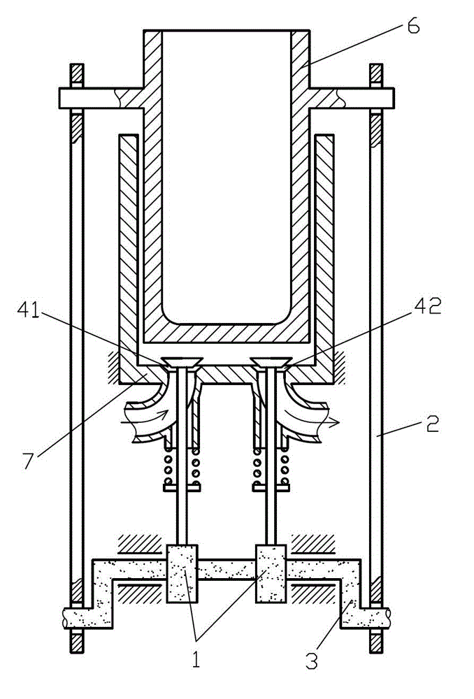
[0046] like figure 1 The shown crankshaft cam gas distribution mechanism includes a gas distribution displacement member, a gas distribution seat port and a cam 1, the gas distribution seat port is arranged on the cylinder mechanism fixing part of the cylinder piston mechanism, and the gas distribution displacement member is connected to the The air distribution seat port is matched, the cylinder mechanism slider of the cylinder piston mechanism is rotationally connected with the connecting rod journal of the crankshaft 3 through the connecting rod 2, the cam 1 is arranged on the main journal of the crankshaft 3 and controls the distribution The air displacement member distributes air to the cylinder-piston mechanism.

[0047]In this embodiment, the gas distribution displacement member is configured as a gas distribution valve, the piston of the cylinder-piston mechanism is configured as a sliding piston 6, the cylinder liner of the cylinder-piston mechanism is configured as ...

Embodiment 2

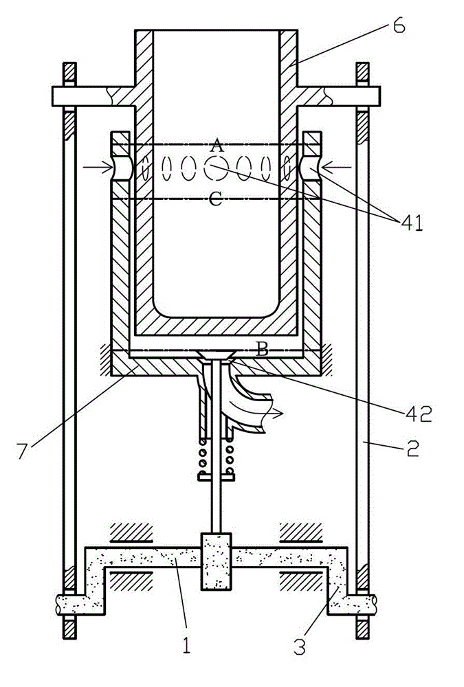
[0053] like figure 2 The difference between the shown crankshaft cam valve mechanism and Embodiment 1 is that the air inlet 41 is arranged on the side wall of the fixed cylinder liner 7 , specifically at the bottom dead center of the sliding piston 6 nearby location.

[0054] This embodiment can work according to the two-stroke engine working mode. When the sliding piston 6 is at the bottom dead center A, the air inlet 41 and the exhaust port 42 are in an open state, and the air inlet 41 is in an open state. A scavenging pump is connected, and the scavenging pump feeds compressed gas into the cylinder of the cylinder-piston mechanism to force the scavenging to discharge the residual exhaust gas in the cylinder. When the sliding piston 6 moves to the upper dead center, before closing the air inlet 41, The exhaust valve controlled by the cam 1 is closed first, and when the sliding piston 6 is close to the top dead center B, fuel injection ignition is performed, and the sliding...

Embodiment 3

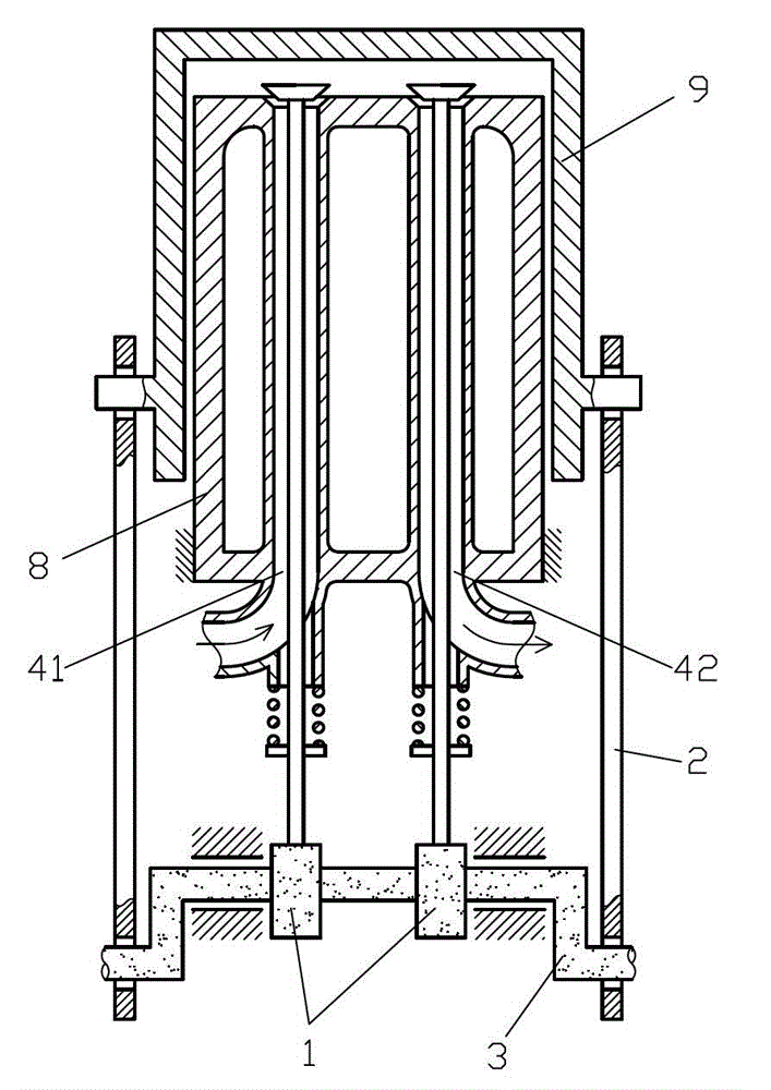
[0056] like image 3 The shown crankshaft cam valve mechanism differs from Embodiment 1 in that the piston of the cylinder-piston mechanism is set as a fixed piston 8, the cylinder liner of the cylinder-piston mechanism is set as a sliding cylinder liner 9, and the cylinder liner of the cylinder-piston mechanism is set as a sliding cylinder liner 9. The fixed part is set as the fixed piston 8, the sliding part of the cylinder mechanism is set as the sliding cylinder liner 9, and an air distribution seat is set on the fixed piston 8, and the air distribution seat includes an air inlet 41 and An exhaust port 42, an intake valve is set at the intake port 41, an exhaust valve is set at the exhaust port 42, and the intake valve and the exhaust valve are respectively controlled by two cams 1 control.


PUM


Abstract

The invention discloses a crank cam valve actuating mechanism which comprises a valve actuating displacement element, a valve actuating seat hole and a cam, wherein the valve actuating seat hole is arranged on a cylinder mechanism fixing element of a cylinder piston mechanism; the valve actuating displacement element is matched with the valve actuating seat hole; a cylinder mechanism sliding element of the cylinder piston mechanism is in rotating connection with a connecting rod shaft neck of a crank by a connecting rod; and the cam is arranged on a main shaft neck of the crank and is used for controlling the valve actuating displacement element to carry out valve actuation on the cylinder piston mechanism. The crank cam valve actuating mechanism disclosed by the invention has the advantages of simple structure, low manufacture cost, high reliability and accurate valve actuation.

Description

technical field [0001] The invention relates to the field of thermal energy and power and gas compression of a compressor, in particular to a cylinder-piston mechanism. Background technique [0002] Piston engine, piston gas compressor and piston working mechanism, in the course of work, at least need intake valve and exhaust valve, traditional method is to control described intake valve and / or valve by arranging separate camshaft and cam Or the exhaust valve, this method is due to the existence of a separate camshaft, and the driving of the camshaft needs to be transmitted from the crankshaft through multiple gears or other complicated mechanisms, which makes the valve mechanism quite complicated and the manufacturing cost is high. Therefore, it is necessary to invent a piston-cylinder mechanism with few parts and simple structure of the valve mechanism. Contents of the invention [0003] In order to solve the above problems, the technical scheme proposed by the present ...

Claims


Application Information

Patent Timeline
Patent Type & Authority Patents(China)
IPC IPC(8): F01L1/06F01L1/12F02F11/00F02B75/28F04B39/00
Inventor 靳北彪
Owner 山东八零特种电缆有限公司
Why Eureka
Try Eureka