Energy flow analysis-based vehicle energy management system and method

An energy flow and vehicle technology, applied in the direction of coolant flow control, engine cooling, lubricant pressure control, etc., can solve the problem that the energy consumption of the car cannot be reduced to achieve the best, and achieve reduced energy loss and low engine friction The effect of loss and reduction of energy

Inactive Publication Date: 2012-06-13
CHONGQING CHANGAN AUTOMOBILE CO LTD
View PDF5 Cites 5 Cited by
  • Summary
  • Abstract
  • Description
  • Claims
  • Application Information

AI Technical Summary

Problems solved by technology

From the above analysis, it can be seen that the sum of windage loss, rolling resistance, braking, transmission loss and energy loss caused by vehicle load only accounts for about 21%-27% of the overall energy loss. Optimizing design, reducing rolling resistance, improving electrical load, braking energy recovery

Method used


Image

  • Energy flow analysis-based vehicle energy management system and method
  • Energy flow analysis-based vehicle energy management system and method

Examples


Embodiment Construction

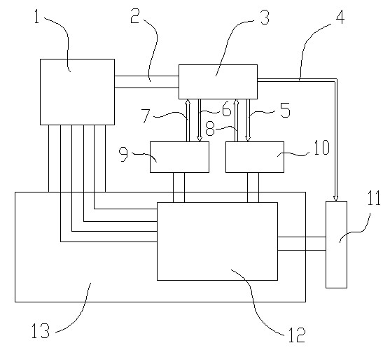
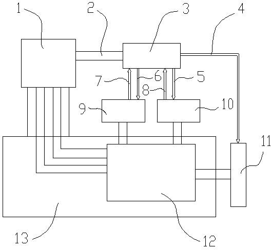
[0016] like figure 1 As shown, the vehicle energy management system based on energy flow analysis includes a vehicle electronic control management system 1, an electronic control unit 3, a CAN bus 2, a water pump flow control device 9, an oil pump flow control device 10 and an idle start-stop device 11, The electronic control unit 3 is connected to the vehicle electronic control management system 1 through the CAN bus 2, and is connected to the water pump flow control device 9 through the water pump flow signal input line 7 and the water pump flow control signal output line 6, and is connected to the water pump flow control device 9 through the oil pump flow signal input line 8 and The oil pump flow control signal output line 5 is connected to the oil pump flow control device 10 , and is connected to the idle start-stop device 11 through the idle start-stop control signal output line 4 .

[0017] The vehicle energy management method based on energy flow analysis is pre-stored ...


PUM


Abstract

The invention relates to an energy flow analysis-based vehicle energy management system and an energy flow analysis-based vehicle energy management method. The energy flow analysis-based vehicle energy management system comprises a vehicle electronic control management system, an electronic control unit, a control area network (CAN) bus, a water pump flow control device, an oil pump flow control device and an idle start-stop device. According to the system and the method, energy loss of an engine is reduced by controlling the cooling, lubrication and idle running of the engine.

Description

technical field [0001] The invention relates to a system and method for energy management of automobiles, in particular to a vehicle energy management system and method based on energy flow analysis. Background technique [0002] From the typical energy distribution of a traditional car, only 22.6% of the energy released by the fuel during combustion finally reaches the wheels, and 87.4% of the energy is lost in the transmission process. Among them, the loss caused by the engine accounted for 62.4% of the total energy loss, the idling loss accounted for 17.2%, the transmission system loss was 5.6%, the braking loss was 5.8%, the driving loss was 4.2%, the aerodynamic loss was 2.6%, and the accessory loss was 2.2%. %. During the actual driving process of the vehicle, the actual proportion of the loss of each system will change with the change of the working conditions. From the above analysis, it can be seen that the sum of windage loss, rolling resistance, braking, transmi...

Claims


Application Information

Patent Timeline
IPC IPC(8): F02D29/02F02D43/00F01P7/16F01M1/16
Inventor 陈绪平胡铁刚聂相虹刘斌杨柏林
Owner CHONGQING CHANGAN AUTOMOBILE CO LTD
Why Eureka
Try Eureka