
Different material interface test device under uniformly distributed load and photoelastic test method

A technology of uniformly distributed load and test device, which is applied in the field of foundation and foundation engineering test research, can solve problems such as complex mechanisms, and achieve the effects of strong repeatability, easy operation, and accurate data

Inactive Publication Date: 2012-06-13
TONGJI UNIV
View PDF2 Cites 12 Cited by
  • Summary
  • Abstract
  • Description
  • Claims
  • Application Information

AI Technical Summary

Problems solved by technology

Continuous features and bulk features can be converted to each other under certain conditions, but the mechanism is extremely complicated
The existing foundation additional stress and settlement calculation theory is based on the continuum mechanics theory for relatively many studies on horizontal stratification, but combined with the granular material mechanics theory for different structures, different foundation treatment forms, different foundation properties and other conditions The additional stress distribution and transmission in the vertical interface layer and the calculation of foundation settlement (deformation) are seldom studied, especially for the lack of understanding of the mechanical mechanism of uneven foundation settlement under embankment loads, only qualitative understanding, so At this stage, there is no additional stress and settlement calculation method for uneven subgrade settlement

Method used


Image

  • Different material interface test device under uniformly distributed load and photoelastic test method
  • Different material interface test device under uniformly distributed load and photoelastic test method
  • Different material interface test device under uniformly distributed load and photoelastic test method

Examples


Embodiment Construction

[0033] The present invention will be further described below in conjunction with the embodiment shown in the accompanying drawings, so that those skilled in the art understand:

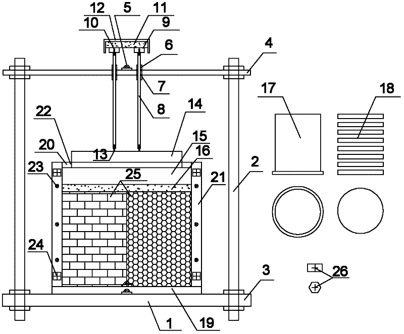
[0034] The test device of the present invention comprises a test platform, a loading system and a model box device such as figure 1 As shown, the model box device is placed on the test platform; the loading system is placed on the upper part of the test platform to apply vertical pressure to the model box device.

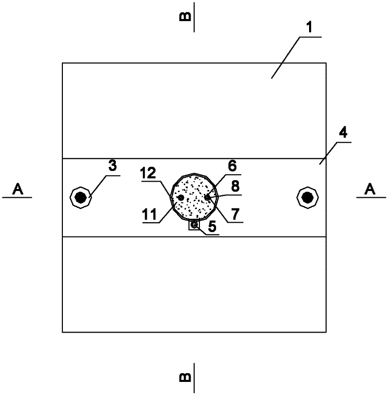
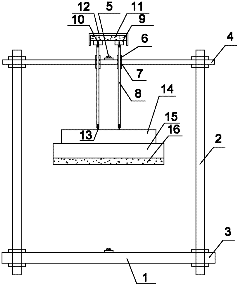
[0035] Among them, the test platform includes a test base platform 1, a test support screw 2, a fixed nut 3, a test top platform 4, and a leveling bubble device 5, such as Figure 1-4 As described above, the test support screw 2 penetrates the test base platform 1 and the test top platform 4 respectively, and the test base platform 1 and the test top platform 4 are parallel, and the test base platform 1 and the test support screw 2, the test base platform 1 and the test support screw 2 are ...


PUM


Abstract

The invention discloses a different material interface test device under a uniformly distributed load and a photoelastic test method. The test device comprises a test platform, a model box device and a loading system, wherein the model box device is arranged on the test platform; both the model box device and the test platform are horizontally arranged; and the loading system is arranged at the upper part of the test platform and used for loading the uniformly distributed load to the model box device. The photoelastic test method comprises the steps of: building and adjusting the model test platform by adopting the different material interface test device according to test requirements, processing a model material, arranging and adjusting the test model box device after a cross cursor is arranged, selecting and adjusting the load loading system, and carrying out post-treatment on the test data by combining with reference ratio basis points through a non-contact photoelectric data collection system. According to the different material interface test device and the photoelastic test method disclosed by the invention, stress transmission and deformation data inside the model material, especially two different material side interferences, can be obtained in real time; and accurate test data can be provided for theoretical and practical engineering researches. The different material interface test device has the advantages of simple structure, easy operation, strong repeatability, accurate data and good test effect.

Description

technical field [0001] The invention belongs to the field of foundation and foundation engineering test research, and in particular relates to a photoelastic model test device and method for simulating the transmission mechanism and deformation analysis of the additional stress of the boundary layer under the uniform load of materials with different foundation soil properties. Background technique [0002] According to the State Council's "Medium and Long-Term Railway Network Planning", by 2020, my country's railways will build "four vertical and four horizontal" railway express passenger transport channels and three intercity passenger transport systems in the Bohai Rim, Yangtze River Delta, and Pearl River Delta areas, and build passenger dedicated lines 1.6 More than 10,000 km. In addition, in order to improve the railway freight transportation capacity, during the "Eleventh Five-Year Plan" period, my country has realized a national railway 28,000 km heavy-duty transportat...

Claims


Application Information

Patent Timeline
Patent Type & Authority Applications(China)
IPC IPC(8): G01L1/24G01B11/16
Inventor 王长丹周顺华王炳龙代仁平季昌
Owner TONGJI UNIV
Learn More