Gait detection device of foot drop corrector

A technology of gait detection and orthosis

Active Publication Date: 2012-06-20
JIANGSU NEUCOGNIC MEDICAL
View PDF3 Cites 17 Cited by
  • Summary
  • Abstract
  • Description
  • Claims
  • Application Information

AI Technical Summary

Problems solved by technology

However, the pressure sensor of the current wireless gait detection device is placed under the patient's foot, and the signal processing and transmission device is placed on the upper of the shoe. It is necessary to connect the sensor to the signal processing and transmission device through an interface, which increases the contact failur

Method used


Image

  • Gait detection device of foot drop corrector
  • Gait detection device of foot drop corrector
  • Gait detection device of foot drop corrector

Examples


Embodiment 1

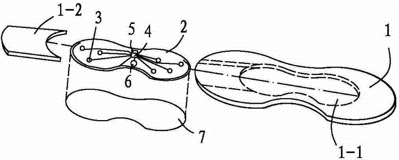
[0024] A kind of foot drop corrector gait detection device embodiment, see figure 1 , there is an insole 1, and a circuit module is arranged in the insole; the circuit module includes a flexible circuit board 2, and a sensor 3, a microprocessor 4, a wireless communication circuit 5 and a battery 6 are distributed and installed on the flexible circuit board. A circuit protection board 7 is arranged below the flexible circuit board, and the protection board is bonded to the bottom side of the flexible circuit board or the insole. The flexible circuit board is a mature technology, which is a flexible copper-clad laminate covered with copper foil on both sides of the epoxy resin glass cloth board of 0.1mm to 0.3mm, and is etched on both sides of the flexible copper-clad laminate by corrosion technology The output circuit forms a flexible circuit board; the sensor is directly connected to the microprocessor and the wireless communication circuit through the circuit on the circuit b...

Embodiment 2

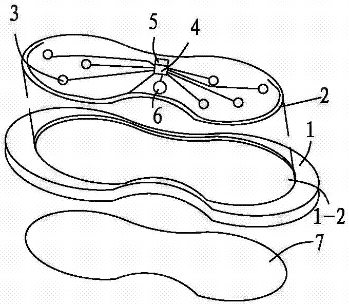
[0027] Another embodiment of a foot drop corrector gait detection device, see figure 2 As in Example 1, the insole is an injection-molded insole. The difference from Example 1 is that the circuit module and the insole are an open structure for the convenience of assembly, and a circuit module with the same shape as the circuit module is arranged on the front or back of the injection-molded insole. The groove is used for placing the circuit module.

Embodiment 3

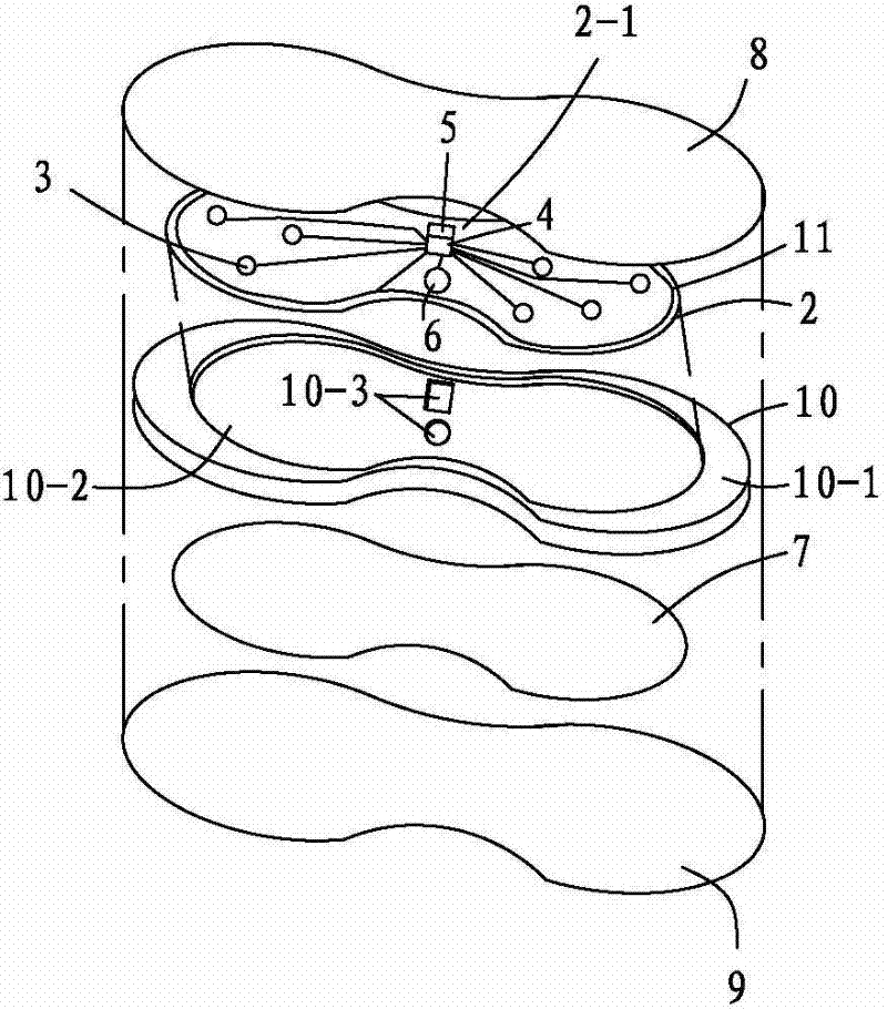
[0029] Another embodiment of a foot drop corrector gait detection device, see image 3 And embodiment 1, different from embodiment 1 is that described insole is a multi-layer insole, and described multi-layer insole includes the insole surface layer 8 that contacts patient's sole and the bottom layer 9 that is connected with the insole of the shoe, wherein , a circuit layer is arranged between the surface layer and the bottom layer of the insole, the circuit layer includes an injection molded board 10 and the flexible circuit board 2, the flexible circuit board is installed in the injection molded board, and the surface of the flexible circuit board faces the bottom layer of the insole It is the lower layer, the microprocessor, the wireless communication circuit chip and the battery are installed on the lower layer of the flexible circuit board, the sensor is installed on the upper layer of the flexible circuit board, and the installation surface of the flexible circuit board o...


PUM


Abstract

The invention relates to a gait detection device of a foot drop corrector. The device is provided with an insole and is characterized in that the insole is provided with a circuit module; the circuit module comprises a flexible circuit board and a circuit protection board; and sensors, a microprocessor, a wireless communication circuit and a battery are distributed and installed on the flexible circuit board. Compared with the prior art, the device has the following beneficial effects: the device has reasonable structure, realizes direct connection between the microprocessor and the wireless communication circuit as well as the sensors and overcomes the defect of generation of the signals and the contact fault of the treatment device; the integral structure brings convenience for the patients; and the defect that errors between the signals of the pressure sensors and the actual gait are generated because the sick foots always fall to the ground unstably when contacting the ground can be overcome by using the flexible steel board as the circuit protection board.

Description

technical field [0001] The invention belongs to the field of medical equipment, and in particular relates to a gait detection device for a foot drop corrector. The device is used to detect the gait and transmits the output to an electric stimulation device for a foot drop corrector. Background technique [0002] Stroke, traumatic brain injury, spinal cord injury, and multiple sclerosis and other central nervous system diseases often cause foot drop. The patient showed that he could not dorsiflex the foot, and when walking, he either dragged the diseased foot or lifted the lower limb of the diseased side higher, so the gait was slow, abnormal, poor in stability, and unable to walk for a long time. This abnormal gait further causes hip, back, and knee joint injuries, seriously affecting the patient's daily life. [0003] The traditional treatment for foot drop is to use a mechanical foot support to fix the foot and lower leg at a vertical angle, mechanically preventing the fo...

Claims


Application Information

Patent Timeline
IPC IPC(8): A61B5/11
Inventor 吴长旺
Owner JIANGSU NEUCOGNIC MEDICAL
Why Eureka
Try Eureka