Electric continuous flow device of circulation loop

A circulation circuit and airflow technology, applied in the field of continuous airflow device of the circulation circuit, can solve the problems of high breathing power consumption, heat loss, large resistance, etc., and achieve the effect of ensuring medical safety and stable working status

Active Publication Date: 2012-06-20
李恩有 +3
View PDF8 Cites 0 Cited by
  • Summary
  • Abstract
  • Description
  • Claims
  • Application Information

AI Technical Summary

Problems solved by technology

[0004] The present invention solves the problem of the semi-open anesthesia circuit used in pediatric anesthesia. The high-flow fresh airflow can make the airway of children dry, heat loss, and respiratory efficiency low. In addition, during the operation anesthesia process, the body absorbs and utilizes very little oxygen and volatile anesthetics. , a large amount of unused oxygen and volatile anesthetics are discharged into t

Method used


Image

  • Electric continuous flow device of circulation loop
  • Electric continuous flow device of circulation loop
  • Electric continuous flow device of circulation loop

Examples


specific Embodiment approach 1

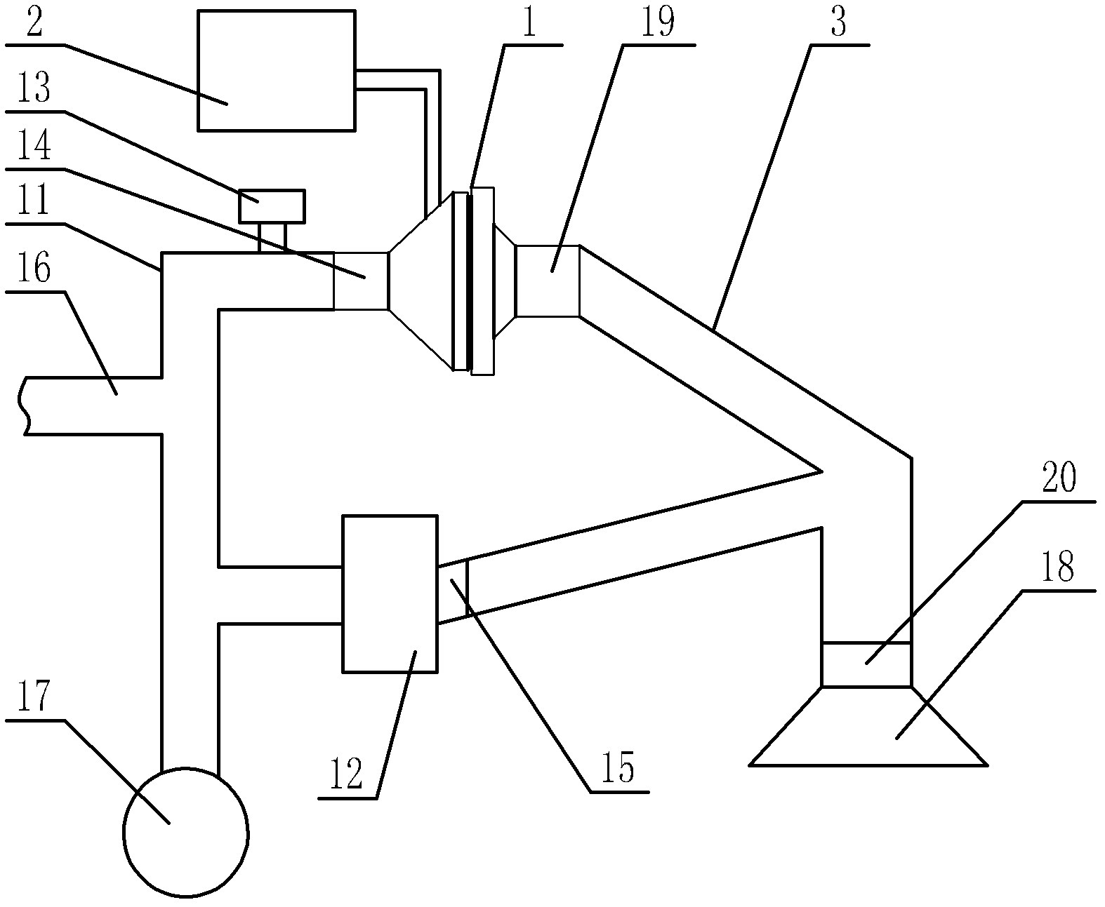
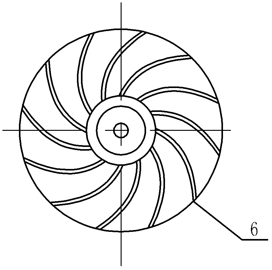
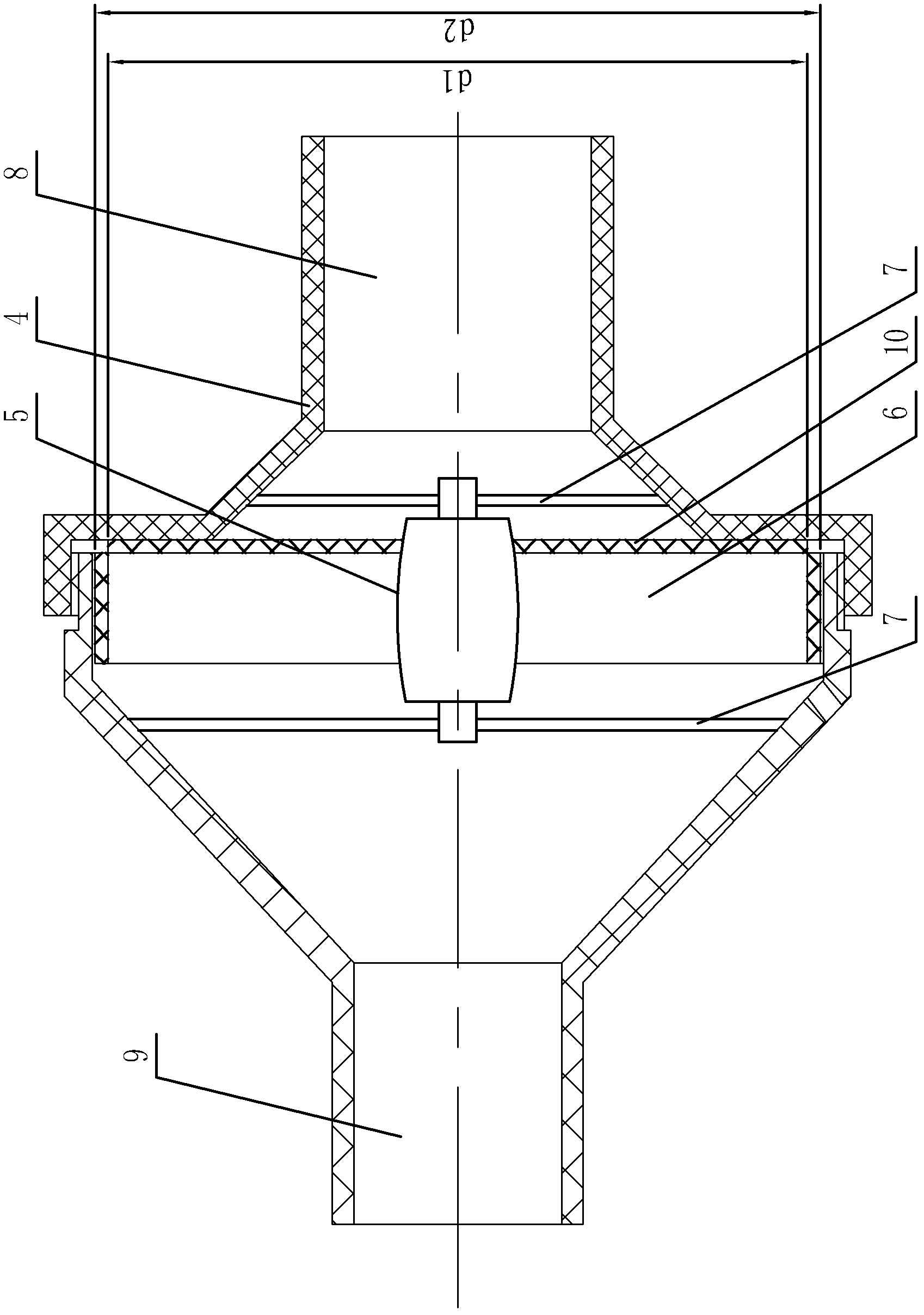
[0014] Specific implementation mode one: combine Figure 1-Figure 3 Describe this embodiment, the circulation loop electric continuous air flow device of this embodiment, the air flow device includes an outer rotor axial flow fan 1, a touch screen 2 and a disposable anesthesia circuit 3, and the outer rotor axial flow fan 1 includes a fan housing 4, Outer rotor motor 5, fan blades 6 and multiple support rods 7; the disposable anesthesia circuit 3 is provided with an inhalation port 19, an exhalation port 20 and a circuit exhalation interface 14; the outer rotor motor 5 is installed in the fan housing 4, and the fan blades 6 is installed on the rotor of the outer rotor motor 5, the motor shaft of the outer rotor motor 5 is used as a stator, and the two ends of the motor shaft of the outer rotor motor 5 are fixedly connected to the inner side wall of the fan casing 4 through a plurality of support rods 7 respectively, and the fan casing One end interface of 4 is an air inlet 8, ...

specific Embodiment approach 2

[0017] Specific implementation mode two: combination figure 2 Note that the thickness of the disk-shaped flow guide plate 10 of this embodiment is 2 mm. The strength of the disc-shaped guide vane can be guaranteed. Other components and connections are the same as those in the first embodiment.

specific Embodiment approach 3

[0018] Specific implementation mode three: combination figure 2 It is explained that the disk-shaped guide vanes 10 and the fan blades 6 of this embodiment are fixedly connected by bonding. Other components and connections are the same as those in the first embodiment.


PUM

PropertyMeasurementUnit
Thicknessaaaaaaaaaa

Abstract

An electric continuous flow device of a circulation circuit relates to a continuous flow device of a circulation loop, and solves the problems that a semi-open anesthetic loop for pediatric anesthesia causes low respiratory efficiency, the unutilized oxygen and volatile anesthetics are discharged into the atmosphere, medical resources are wasted, the environment is polluted, and a pediatric anesthetic close circulation loop has large resistance and high respiratory power consumption. A disc flow deflector is fixedly installed on a fan blade and is positioned at one side of an air inlet side, the external diameter of the disc flow deflector is d1, the external diameter of the fan blade is d2, and di equals to d2 minus 4mm; and the control signal output end of a touch screen is connected with the control signal input end of an external rotor electric machine, the signal output end of the external rotor electric machine is connected with the signal input end of the touch screen, the loop inspiration port of a respiration loop is communicated with the inspiration end of a disposable anesthetic loop through the external rotor electric machine, and the loop expiration port of the disposable anesthetic loop is communicated with a respiration loop through a dioxide carbon absorption unit. The electric continuous flow device is used in the anesthetic loop systems for children and adults.

Description

technical field [0001] The invention relates to a continuous airflow device for a circulation loop, which belongs to the technical field of anesthesia medical equipment. Background technique [0002] The anesthesia circuits used in pediatric anesthesia centers mostly use semi-open circuits, which are widely used due to their advantages of low resistance, low breathing power consumption, and taking into account both controlled breathing and spontaneous breathing. The flow of fresh air can dry out a child's airway, leading to heat loss and inefficient breathing. In order to solve spontaneous breathing and control breathing, various circuits need to be designed and produced. In the process of surgical anesthesia, the body absorbs and utilizes very little oxygen and volatile anesthetics, and a large amount of unused oxygen and volatile anesthetics are discharged into the atmosphere, wasting precious medical resources and seriously polluting the environment. [0003] Due to the...

Claims


Application Information

Patent Timeline
IPC IPC(8): A61M16/01
Inventor 李恩有孙波樊世新赵嘉训
Owner 李恩有
Why Eureka
Try Eureka