Dust removing device for flue gas

A dust removal device and flue gas technology, applied in the use of liquid separation agent, lighting and heating equipment, separation of dispersed particles, etc., can solve the problems of mixed contact, low dust removal performance and efficiency, and incomplete dust removal

Inactive Publication Date: 2012-06-20
SHENYANG CHUANGDA TECH TRADE MARKET
View PDF0 Cites 10 Cited by
  • Summary
  • Abstract
  • Description
  • Claims
  • Application Information

AI Technical Summary

Problems solved by technology

However, the disadvantage of this dust removal device is that the dusty flue gas cannot be fully mixed with water, the dust removal is not complete, and the dust removal performance and efficiency are low.

Method used


Image

  • Dust removing device for flue gas
  • Dust removing device for flue gas

Examples


Embodiment Construction

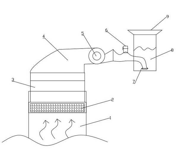
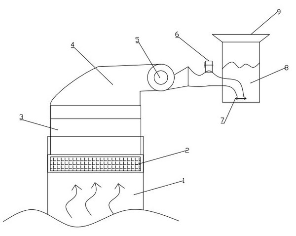
[0009] In order to gain an in-depth understanding of the structure of the improved flue gas dedusting device, combined with figure 1 described as follows:

[0010] Flue gas dedusting device, heat exchange device 2 is installed at the outlet of flue 1, and then connected to fume hood 3 to guide the cooled flue gas to shroud 4 connected to fume hood 3; Pass into exhaust valve 7, exhaust valve 7 is placed in the bottom in water tank 8, fill water in water tank 8, water surface height has not crossed exhaust valve 720cm, and protective cap 9 is installed on the top of water tank 8. The exhaust valve 7 leads into the water, with the opening downward, and the flue gas passes through the exhaust valve 7 into the water and is filtered; the exhaust valve 7 is provided with a one-way pressure valve to prevent water from entering the exhaust valve 7. A pressure reducing valve 6 is arranged on the pipeline connecting the exhaust fan 5 and the exhaust valve 7 .

[0011] The flue gas prod...


PUM


Abstract

A dust removing device for flue gas belongs to the field of manufacturing of metallurgy equipment. A heat exchange device is arranged at an outlet of a flue duct and connected with a smoke hood; cooled flue gas is guided to an air guide sleeve connected with the smoke hood; an exhaust blower is mounted on the air guide sleeve; flue gas is pumped in an exhaust valve through a pipeline; the exhaust valve is arranged at the bottom of a water tank; the water tank is filled with water, and the water surface submerges the exhaust valve for 20 cm; and a protective cap is mounted at the top end of the water tank. Flue gas generated when fuels are combusted can be guided in the bottom of the water tank and forms intensive small air bubbles in water to rise; the flue gas containing dust can fully contact with water, solid dust and certain harmful gas soluble in water are adsorbed by water, so that the flue gas is purified and is discharged from the upper end of the water tank; and a pressure reducing valve can adjust the pressure when the flue gas is pumped in the water tank.

Description

technical field [0001] The invention relates to a flue gas dedusting device, which belongs to the field of metallurgical manufacturing equipment. Background technique [0002] The flue gas produced by the combustion of fuels such as coal and organic waste contains a large amount of dust and harmful gases. These air pollutants will cause great pollution to the surrounding environment. There are many flue gas dedusting devices at present, one of which is to make the flue gas flow pass through water to make it mix and contact with water, and remove dust and harmful gases through the adsorption of water. However, the disadvantage of this dust removal device is that the dusty flue gas cannot be fully mixed with water, the dust removal is not complete, and the dust removal performance and efficiency are low. Contents of the invention [0003] In view of the defects in the prior art, the object of the present invention is to provide a flue gas and dust removal device that can fu...

Claims


Application Information

Patent Timeline
Patent Type & Authority Applications(China)
IPC IPC(8): B01D47/02B01D53/18F23J15/00
Inventor 王爽刘涛
Owner SHENYANG CHUANGDA TECH TRADE MARKET
Why Eureka
Try Eureka