Two-phase carbon dioxide collecting device

A carbon dioxide, circulating pump technology, applied in inorganic chemistry, carbon compounds, chemical instruments and methods, etc., can solve the problem of high energy consumption, achieve the effect of strong absorption capacity and cost reduction

Active Publication Date: 2012-06-20
TSINGHUA UNIV
View PDF2 Cites 22 Cited by
  • Summary
  • Abstract
  • Description
  • Claims
  • Application Information

AI Technical Summary

Problems solved by technology

However, a common problem faced by the current chemical absorption technology is high energy consumption, especially the regeneration process of the absorbent

Method used


Image

  • Two-phase carbon dioxide collecting device
  • Two-phase carbon dioxide collecting device

Examples


Embodiment 1

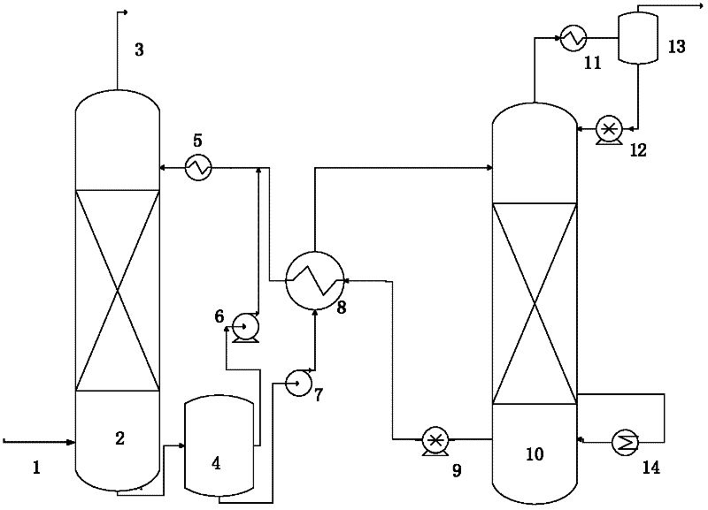
[0019] A two-phase carbon dioxide capture device (such as figure 1 shown), the bottom of the absorption tower 2 is connected with the separator 4, the middle or upper part of the separator 4 is connected with the first circulating pump 6, the bottom of the separator 4 is connected with the second circulating pump 7, and the first circulating pump 6 is connected with the The first heat exchanger 5 is connected to the top of the absorption tower 2, the second circulating pump 7 is connected to the poor-rich liquid heat exchanger 8, and the rich liquid heat exchanger 8 is respectively connected to the first heat exchanger 5, the top of the desorption tower 10, The third circulating pump 9 is connected, the third circulating pump 9 is connected with the bottom of the desorption tower 10, the regeneration device 14 is connected with the bottom of the desorption tower 10, and the top of the desorption tower 10 is connected with the second heat exchanger 11 and the fourth circulation ...

Embodiment 2

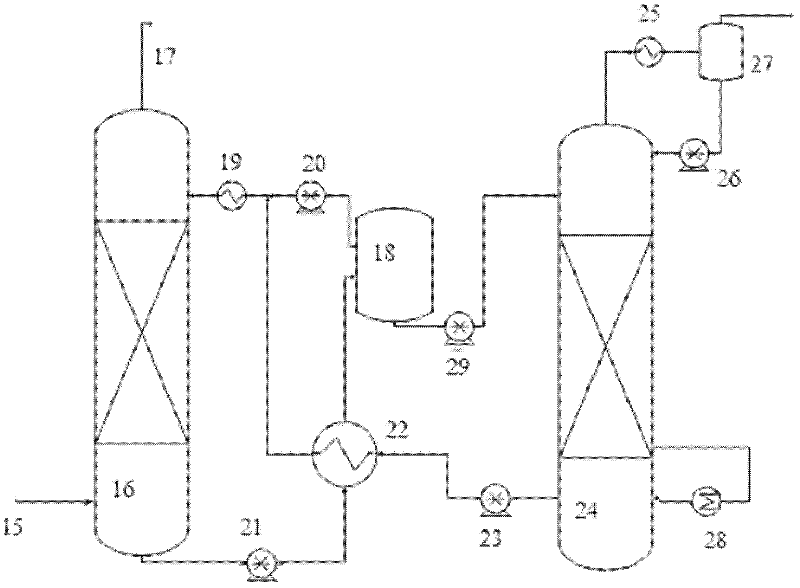
[0023] A two-phase carbon dioxide capture device (such as figure 2shown), the bottom of the absorption tower 16 is sequentially connected with the first circulation pump 21 and the lean-rich liquid heat exchanger 22, and the lean-rich liquid heat exchanger 22 is respectively connected with the first heat exchanger 19, the separator 18, and the second circulation pump 23 is connected, the third circulation pump 20 is connected with the first heat exchanger 19, the separator 18 is connected with the third circulation pump 20 and the fourth circulation pump 29 respectively, the second circulation pump 23 is connected with the bottom of the desorption tower 24, and the fourth Circulation pump 29 links to each other with the top of desorption tower 24, and regeneration unit 28 is connected at the bottom of desorption tower 24, and the top of desorption tower 24 connects the second heat exchanger 25 and the 5th circulation pump 26 respectively, the second heat exchanger 25 and the 5...


PUM


Abstract

The invention discloses a two-phase carbon dioxide collecting device which belongs to the technical field of flue gas cleaning treatment. Compared with the conventional collecting device, the two-phase carbon dioxide collecting device is additionally provided with a separator, wherein an absorbent solution in the separator is separated into two liquid phases, of which the carbon dioxide contents are obviously different; upper layer liquid is separated from lower layer liquid by standing, performing rotary centrifugal separation or filtering; and the upper layer liquid is directly recycled, and the lower layer liquid is conveyed into an absorption tower for regeneration. By adoption of the two-phase carbon dioxide collecting device, the energy consumption by a chemical absorption method for collecting the carbon dioxide is greatly reduced, and then the cost for large-scale application of the technology is reduced.

Description

technical field [0001] The invention belongs to the technical field of flue gas purification treatment, and in particular relates to a two-phase carbon dioxide capture device. Background technique [0002] Due to the sharp increase in carbon dioxide emissions and the intensification of the greenhouse effect, the temperature of the earth's surface has risen, glaciers have melted, sea levels have risen, and extreme weather events have occurred frequently. Therefore, it is imperative to control carbon dioxide emissions. [0003] The existing capture technologies mainly include pre-combustion capture, post-combustion capture and oxygen-enriched combustion technology. Among them, post-combustion capture includes technologies such as chemical absorption, physical adsorption, membrane separation and low temperature separation. Considering the maturity, economy and commercialization level of various existing technologies, chemical absorption is a more commonly used option. [0004...

Claims


Application Information

Patent Timeline
Patent Type & Authority Applications(China)
IPC IPC(8): B01D53/18C01B31/20C01B32/50
CPCY02P20/151
Inventor 王淑娟徐志成刘今朝高巨宝周姗赵博陈昌和
Owner TSINGHUA UNIV
Why Eureka
Try Eureka