Supercharge Your Innovation With Domain-Expert AI Agents!

Machining method of step end face balance hole

A processing method and technology for balancing holes, which are applied in metal processing equipment, metal processing mechanical parts, manufacturing tools, etc., can solve the problems such as the inability to guarantee the dimensional accuracy of the balancing holes and the low precision of the step end face of the steam turbine rotor, and achieve optimal allowance distribution. and cutting parameters, the effect of improving processing efficiency and improving service life

Inactive Publication Date: 2012-06-20
HARBIN TURBINE
View PDF6 Cites 5 Cited by
  • Summary
  • Abstract
  • Description
  • Claims
  • Application Information

AI Technical Summary

Problems solved by technology

[0003] The present invention aims to solve the problem of low precision of the step end face of the steam turbine rotor processed by the existing method, and provides a processing method for the balance hole of the step end face
[0005] The beneficial effects of the present invention are: after careful analysis and research on the processing status of the balance hole of the step end face of the steam turbine rotor, the use of a special fixture with high positioning accuracy enables the precise positioning of the steam turbine rotor with the step end face, and greatly reduces the number of cutting tools during processing. Deflection and vibration, which solves the problem that the dimensional accuracy of the balance hole cannot be guaranteed by direct drilling

Method used


Image

  • Machining method of step end face balance hole
  • Machining method of step end face balance hole
  • Machining method of step end face balance hole

Examples


specific Embodiment approach 1

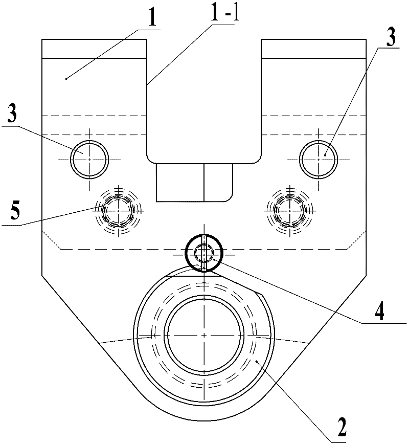
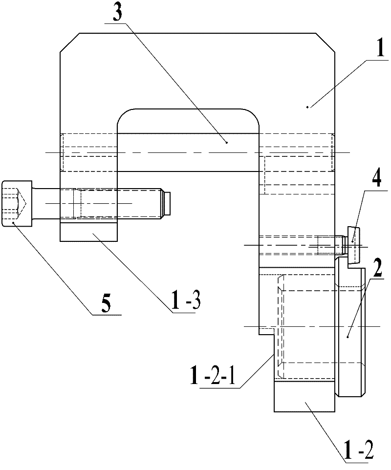
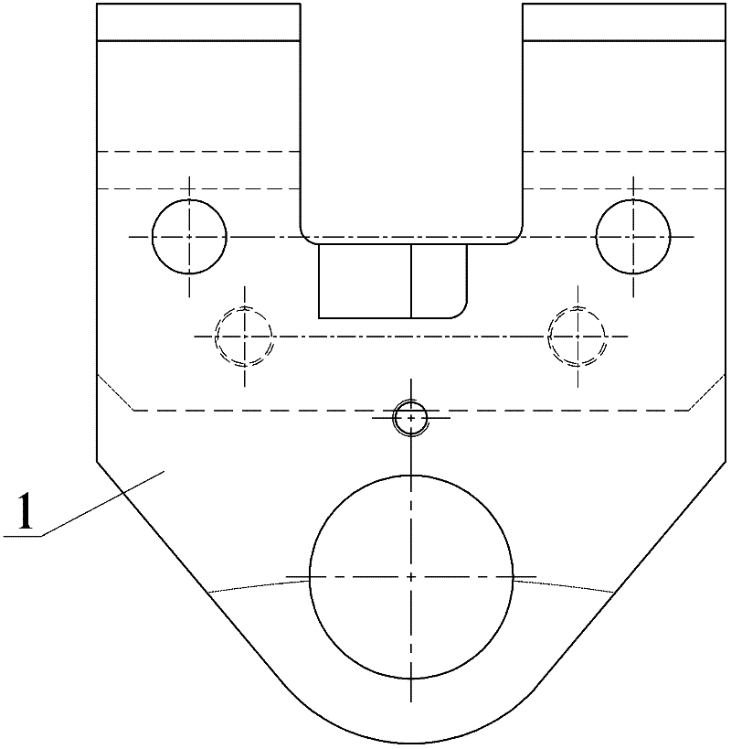
[0009] Embodiment 1: A processing method for the balance hole on the end face of a step is carried out according to the following steps: 1. Drilling: according to the set hole position, the special fixture is positioned and installed on the rotor end face of the pre-drilled hole, and the Φ30 drill sleeve and the drill sleeve are installed. Φ30 drill bit, and clamp the drill sleeve on the clamp body, use the Φ30 drill bit to drill, the cutting parameters are: speed 160-200r / min, feed rate 0.25-0.35mm / r; 2. Reaming: after drilling is completed , remove the Φ30 drill sleeve, install the Φ37.5 drill sleeve and the Φ37.5 reamer, and clamp the drill sleeve on the clamp body, use the Φ37.5 reamer to ream the hole, and the cutting parameters are: speed 125~160r / min, feed rate 0.3~0.4mm / r; 3. Reaming: After reaming, remove the Φ37.5 drill sleeve, install the Φ38 drill sleeve and Φ38 reamer, and clamp the drill sleeve on the clamp body , using a Φ38 reamer for reaming, the cutting para...

specific Embodiment approach 2

[0011] Embodiment 2: This embodiment differs from Embodiment 1 in that the inner side of the long side wall 1-2 of the special fixture is provided with a shoulder 1-2-1.

specific Embodiment approach 3

[0012] Specific embodiment three: the difference between this embodiment and specific embodiment one is that the shaft end of the drill sleeve 2 is provided with a small shoulder 2-1, and the small shoulder 2-1 is used to correspond to the nail cap of the drill sleeve set screw 4 Cooperate, the end face of the shaft end of the drill bushing 2 is in an excellent arc shape.


PUM


Abstract

The invention relates to a machining method of a step end face balance hole, in particular to the machining method of the end face balance hole. The technical problem that the precision requirements of the size of the balance hole cannot be met in the prior art needs to be solved by the invention. The machining method of the step end face balance hole comprises the following steps of: firstly, installing a special clamp on a rotor end face to be pre-drilled, and using a phi 30 drill to drill; secondly, using a phi 37.5 hole expanding drill to expand the hole; thirdly, using a phi 38 reamer to ream; and fourthly, repeating the steps one to three, and realizing the machining of all balance holes of the rotor end face one by one. The machining method of the step end face balance hole solves the problems that the machining of the size of the step end face balance hole is ultra-poor. The surface roughness of the balance hole machined by the method provided by the invention is increased to Ra0.4-Ra0.8 from Ra1.6. The machining method of the step end face balance hole is used for machining the step end face balance hole of a turbine rotor.

Description

technical field [0001] The invention relates to a processing method of an end face balance hole. Background technique [0002] When machining the balance hole on the end face of the steam turbine rotor, because the steam turbine rotor is not easy to fix, the tool deflection and vibration are large, resulting in inaccurate positioning of the machined balance hole and out-of-tolerance dimensions, resulting in low machining accuracy, especially in the case with steps When the balance hole is processed on the end face, the situation is even more serious. The prior art does not provide a method for specially processing the balance hole on the end face of the step. Contents of the invention [0003] The invention aims to solve the problem of low precision of the step end face of the steam turbine rotor processed by the existing method, and provides a processing method for the balance hole of the step end face. [0004] The specific steps of the processing method of a step end f...

Claims


Application Information

Patent Timeline
IPC IPC(8): B23P17/00B23Q3/00B23B47/28
Inventor 孙盛丽魏成双魏崇巍
Owner HARBIN TURBINE
Features
  • R&D
  • Intellectual Property
  • Life Sciences
  • Materials
  • Tech Scout
  • Unparalleled Data Quality
  • Higher Quality Content
  • 60% Fewer Hallucinations
Learn More