Middle trough for composite trough body scraper conveyor

A scraper conveyor and composite groove technology, applied in the field of scraper conveyor, can solve the problems of low production efficiency, unprotected grooves and notch, and high production cost

Inactive Publication Date: 2012-06-20
SHANDONG MINING MASCH GRP CO LTD
View PDF6 Cites 9 Cited by
  • Summary
  • Abstract
  • Description
  • Claims
  • Application Information

AI Technical Summary

Problems solved by technology

However, the baffle plate groove side, the blade groove side, the middle plate and the bottom plate are integrated in the existing middle groove. When the middle plate or the groove side cannot work due to wear and tear, the middle groove where the damaged parts are located must be replaced as a whole. It takes about one shift to replace a section of the middle tank in the underground working face, which is not only labor-intensive and time-consuming, but also has low production efficiency and high production costs
In order to prolong the service life of the middle trough, the Chinese patent No. 200920019382.7 discloses a middle trough of a coal shearer, in which a replaceable wear-resistant functional part is arranged in the upper trough body of the middle trough, and the wear-resistant functional part is compatible with the The basic structural parts are fastened together by welding or bolts, but when replacing the "C"-shaped structural wear-resistant parts, they can only be taken out or loaded through the two ends of the middle groove, and cannot be replaced directly from the upper port. For installation, even if one component is replaced, all the connecting components at both ends of the middle groove must be opened, which is time-consuming and laborious, and the operation is inconvenient. Moreover, after the scraper machine is used, the middle groove is easily deformed, which also brings inconvenience to the replacement of wear-resistant structural parts. ; Furthermore, the middle groove of this structure has no protection for its notch, and its wear resistance is also poor. When the notch is worn out, it is still necessary to replace the entire middle groove
The Chinese patent application with the application number 201010608258.1 discloses a scraper machine and its middle groove. It is provided with ceramic strips on the middle plate to improve the wear resistance of the middle plate. The manufacturing process of this conveyor is complicated, the cost is high, and The groove side and notch are not protected, and its overall wear resistance is not strong, and after the groove side is worn out, it needs to be replaced as a whole, the production cost is high, and it is laborious

Method used


Image

  • Middle trough for composite trough body scraper conveyor
  • Middle trough for composite trough body scraper conveyor
  • Middle trough for composite trough body scraper conveyor

Examples


Embodiment 1

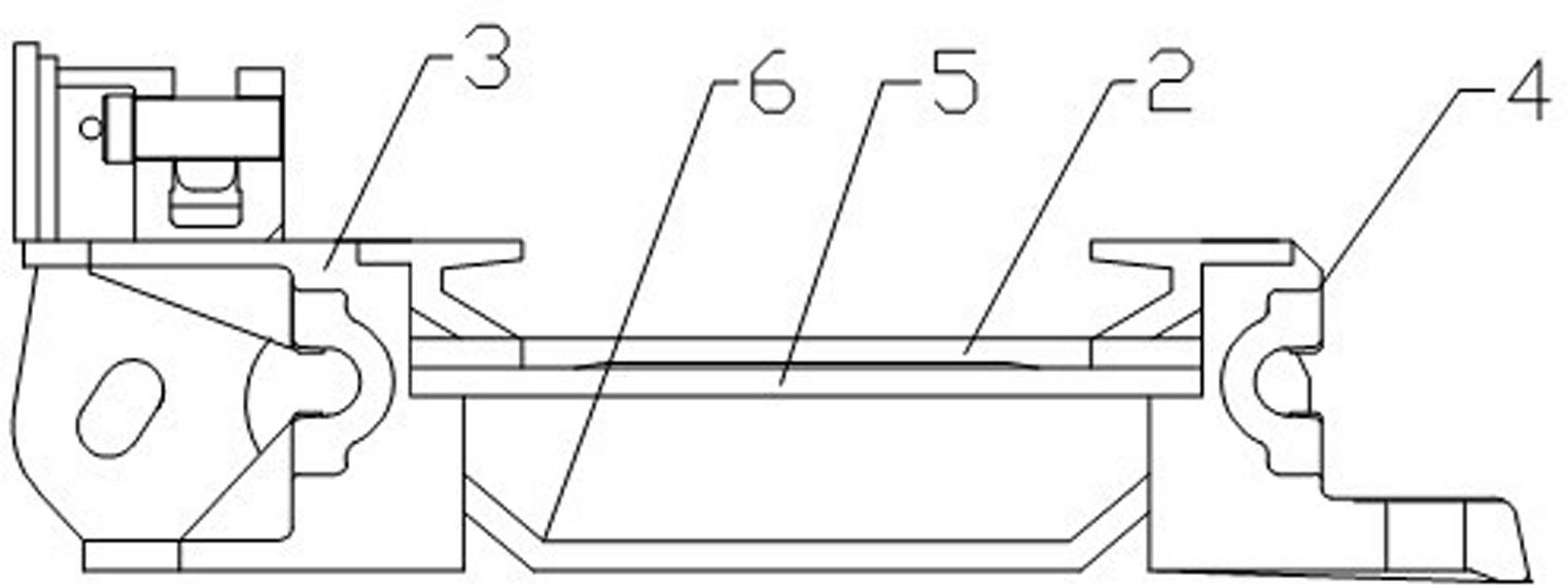
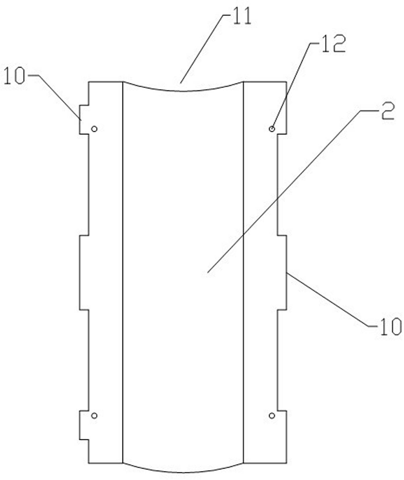
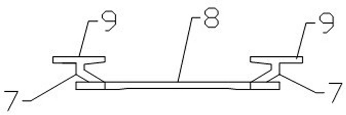
[0015] Embodiment 1: Referring to the accompanying drawings, the middle trough of the composite trough scraper conveyor includes a baffle side 3 , a shovel side 4 , a middle plate 5 and a bottom plate 6 welded together. The angle α between the inner surface of the side of the middle groove and the surface of the middle plate 5 is 90 degrees, and the side 3 of the baffle plate and the side 4 of the spade plate are provided with a limit bayonet 1, which is located on the side of the groove Grooves above. A lining groove 2 is provided in the cavity on the upper part of the middle plate 5, and the lining groove 2 includes a lining groove bottom plate 8 and side plates 7 affixed to both sides in the width direction of the lining groove bottom plate 8, and a wing plate 9 is fixedly connected to the top of the side plate 7. The outer side of the wing plate 9 is provided with a limit clamp 10, and the liner groove 2 cavity is formed by the lining groove bottom plate 8, the side plate ...

Embodiment 2

[0016] Embodiment 2: Referring to the accompanying drawings, the middle trough of the composite trough scraper conveyor includes a baffle side 3 , a shovel side 4 , a middle plate 5 and a bottom plate 6 welded together. The angle α between the inner surface of the side of the middle groove and the surface of the middle plate 5 is 95 degrees, and the side 3 of the baffle plate and the side 4 of the shovel plate are provided with a limit bayonet 1, which is located on the side of the groove Grooves above. A lining groove 2 is provided in the cavity on the upper part of the middle plate 5, and the lining groove 2 includes a lining groove bottom plate 8 and side plates 7 affixed to both sides in the width direction of the lining groove bottom plate 8, and a wing plate 9 is fixedly connected to the top of the side plate 7. The outer side of the wing plate 9 is provided with a limit clamp 10, and the liner groove 2 cavity is formed by the lining groove bottom plate 8, the side plate...

Embodiment 3

[0017] Embodiment 3: Referring to the accompanying drawings, the middle trough of the composite trough scraper conveyor includes a baffle side 3 , a shovel side 4 , a middle plate 5 and a bottom plate 6 welded together. The angle α between the inner surface of the side of the middle groove and the surface of the middle plate 5 is 98 degrees, and the side 3 of the baffle plate and the side 4 of the shovel plate are provided with a limit bayonet 1, which is located on the side of the groove Grooves above. A lining groove 2 is provided in the cavity on the upper part of the middle plate 5, and the lining groove 2 includes a lining groove bottom plate 8 and side plates 7 affixed to both sides in the width direction of the lining groove bottom plate 8, and a wing plate 9 is fixedly connected to the top of the side plate 7. The outer side of the wing plate 9 is provided with a limit clamp 10, and the liner groove 2 cavity is formed by the lining groove bottom plate 8, the side plate...


PUM


Abstract

The invention discloses a middle trough for a composite trough body scraper conveyor. The middle trough comprises a middle trough body, wherein the middle trough body comprises a baffle plate ledge, a shovel plate ledge, a middle plate and a base plate; a lining trough is arranged in a trough cavity on the upper part of the middle plate, and comprises a lining trough base plate and side plates fixedly connected to two sides of the lining trough base plate along the width direction; wing plates are fixedly connected to the tops of the side plates; the cavity of the lining trough is used as an upper scraper chain channel; limiting clamping heads are arranged on the outer sides of the wing plates; an included angle alpha between the inner surface of the ledge of the middle trough and the surface of the middle plate is not less than 90 degrees; limiting clamping openings corresponding to the limiting clamping heads are formed in the baffle plate ledge and the shovel plate ledge; and the limiting clamping heads are correspondingly arranged in the limiting clamping openings. When damaged, the lining trough can be taken down from the trough opening conveniently without opening a middle trough connection piece; time and labor are saved; the middle trough is convenient to maintain quickly; the work efficiency is improved greatly; and the coal mining cost is reduced.

Description

technical field [0001] The invention belongs to the technical field of scraper conveyors, and in particular relates to a middle groove of a scraper conveyor. Background technique [0002] With the improvement of fully mechanized mining technology in coal mines, scraper conveyors are developing in the direction of (super) heavy duty, high power and high reliability. The general-purpose scraper conveyor middle trough is a combined structure, generally including a baffle trough side, a scraper trough side, a middle plate and a bottom plate that are fastened together. The scraper chain on the upper part of the middle plate is used as a coal conveying channel, and the life of its structural components is the key to determining the overall service life of the middle tank. Among them, the middle plate is not only the component that bears the horizontal thrust from the hydraulic support when the scraper conveyor is propelled, but also the carrier for transporting coal. Therefore, ...

Claims


Application Information

Patent Timeline
Patent Type & Authority Applications(China)
IPC IPC(8): B65G19/28
Inventor 方守光张明波
Owner SHANDONG MINING MASCH GRP CO LTD
Why Eureka
Try Eureka