Method for performing radiation test on large antenna based on actual paraboloidal coordinates

A test method and paraboloid technology, applied in directions such as antenna radiation patterns, can solve the problems of antenna performance and design value errors, the failure of the antenna to meet the design requirements, and the inability to complete the measurement of heat flow outside the large antenna, achieving strong universality and optical characteristics. obvious effect

Inactive Publication Date: 2012-06-20
CENT FOR SPACE SCI & APPLIED RES
View PDF4 Cites 2 Cited by
  • Summary
  • Abstract
  • Description
  • Claims
  • Application Information

AI Technical Summary

Problems solved by technology

[0016] However, because the design is based on the ideal paraboloid or the ideal value of the shaped surface to simulate and analyze, but due to the errors introduced in the process of processing, assembly and adjustment, there will always be a certain error between the final performance of the antenna and the design value. Under the circumstances, these errors often cause the antenna to fail to meet the design requirements
[0017] In addition, the aerospace field needs to understand the actual radiation performance of the antenna under the actual space heat flow conditions. Under the current conditions, foreign countries can only conduct small-scale tests, and cannot complete the heat flow measurement of large antennas.

Method used


Image

  • Method for performing radiation test on large antenna based on actual paraboloidal coordinates
  • Method for performing radiation test on large antenna based on actual paraboloidal coordinates
  • Method for performing radiation test on large antenna based on actual paraboloidal coordinates

Examples


Embodiment Construction

[0039] In order to better understand the technical solution of the present invention, the implementation steps of the present invention will be further described below in conjunction with the accompanying drawings.

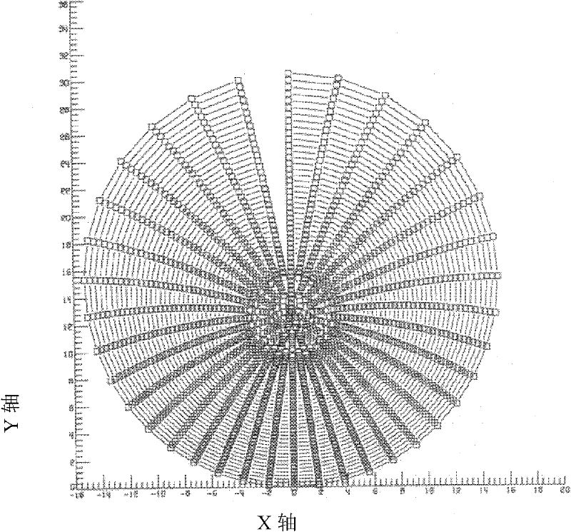
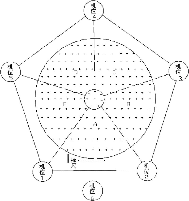
[0040] 1. The shape and surface test of the antenna

[0041] After the antenna processing is completed, its shape and surface test must be carried out. There are many ways to complete the shape and surface test, such as electronic theodolite, three-coordinate system, etc., and an optical photogrammetry system can also be used. Among them, the electronic theodolite test method is the most accurate, but the time is the longest and the most complicated; the photographic test method has the advantages of fast, efficient and simple for low-frequency antennas over several meters, and the test accuracy fully meets the requirements. The optical photographic test of the antenna shape is usually completed with an optical camera and photomodel software. The laser interferom...


PUM


Abstract

The invention relates to a method for performing radiation test on a large antenna based on actual paraboloidal coordinates. According to the method, an actual directional diagram of the antenna is obtained by substituting the actual paraboloidal coordinates into physical optical simulation analysis and calculation. The method comprises the following steps of: 1) performing profile test on the antenna by optical measurement to obtain a reflecting surface coordinate point; and 2) substituting the actually measured antenna profile coordinate point into physical optical calculation to obtain the actual directional diagram of the antenna finally. Or the method comprises the following steps of: 1', obtaining the reflecting surface coordinate point of the antenna profile in external heat flow on the basis of thermal deformation analysis; and 2', performing physical optical calculation by taking the reflecting surface coordinate point of the antenna profile, which is obtained in the step 1', as a reflecting surface to obtain the actual directional diagram of the antenna. The method has the advantages of quickness and convenience, high universality and flexibility.

Description

technical field [0001] The invention belongs to the technical fields of electronics, antenna microwave measurement and aerospace, and particularly relates to a radiation test method of a large antenna based on actual parabolic coordinates. Background technique [0002] Post-fabrication testing of large antennas has long been a challenge. Optical measurement can obtain sufficiently accurate shape error for antennas, but its actual pattern measurement has not been able to be completed. [0003] Due to limited conditions, the quiet zone of the far-field test and the compact field test cannot meet the test conditions for large antennas of several meters or even hundreds of meters; the near-field scanning frame currently only has a travel distance of tens of meters, and the test time is extremely long. The solution to antenna testing is often not to test the radiation characteristics, but only rely on the ideal simulation value during design. Physical optics is an effective mean...

Claims


Application Information

Patent Timeline
Patent Type & Authority Applications(China)
IPC IPC(8): G01R29/10
Inventor 王宏建易敏刘世华陈雪郝齐炎刘广
Owner CENT FOR SPACE SCI & APPLIED RES
Why Eureka
Try Eureka