Shielding insulating body, shielding connector and manufacturing method for shielding connector

A technology of an insulating body and a manufacturing method, which is applied in the field of a shielded insulating body, can solve problems such as cumbersome processing steps, increase production costs, and complex processing techniques, and achieve the effects of reducing production costs, preventing short circuits, and simplifying processing techniques

Active Publication Date: 2014-02-12
DEYI PRECISION ELECTRONIC IND CO LTD PANYU
View PDF5 Cites 0 Cited by
  • Summary
  • Abstract
  • Description
  • Claims
  • Application Information

AI Technical Summary

Problems solved by technology

[0005] This kind of electrical connector is owing to be to form shielding layer by plating conductive layer in described receiving tank first, and plate conductive layer on the bottom surface of described insulating body to form connected conducting layer and lead-out layer, and then to described shielding layer Insulating substances are sprayed with the conductive layer, so it is necessary to set a positioning structure on the bottom surface of the insulating body to cooperate with the stopper to cover part of the conductive layer, which makes it difficult to control the dimensional accuracy of the positioning structure and the stopper, resulting in complicated processing technology; and Since the bottom surface of the insulating body needs to be sprayed with an insulating substance to form the spacer layer after the conductive layer is provided, two steps of assembling the stopper and removing the stopper are required in its manufacturing method, thus resulting in cumbersome processing steps and increasing the production cost. Cost of production

Method used


Image

  • Shielding insulating body, shielding connector and manufacturing method for shielding connector
  • Shielding insulating body, shielding connector and manufacturing method for shielding connector
  • Shielding insulating body, shielding connector and manufacturing method for shielding connector

Examples


specific Embodiment approach

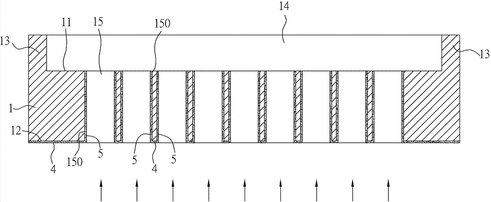
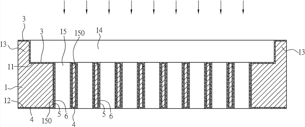
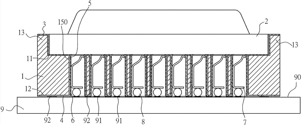
[0035] like figure 1 and figure 2 As shown in , the shielded connector of the present invention includes an insulating body 1 , which is substantially in the shape of a cuboid, and has a top surface 11 and a bottom surface 12 opposite to the top surface 11 . The insulating body 1 is integrally provided with four retaining walls 13 protruding upward from the top surface 11 around the four sides, and the four retaining walls 13 and the top surface 11 form a groove 14 for carrying a chip module 2. The retaining wall 13 can guide the chip module 2 into the groove 14 and limit it. The top and side surfaces of the four retaining walls 13 and the top surface 11 of the insulating body 1 are covered with a first insulating layer 3, the first insulating layer 3 is exposed to the air, and the bottom surface 12 is covered with There is a first metal layer 4, which is exposed to air.

[0036] The insulating body 1 is provided with a plurality of through holes 15 penetrating through th...


PUM


Abstract

The invention discloses a shielding insulating body, a shielding connector and a manufacturing method for the shielding connector. The insulating body is ejection-molded, and comprises a top surface, a bottom surface and a plurality of through holes, wherein the top surface and the bottom surface are opposite to each other; and the plurality of through holes penetrate through the top surface and the bottom surface. A metal material layer is arranged from the bottom surface to the top surface, and covers the bottom surface and the wall surfaces of the through holes; an insulating material layer is arranged from the top surface to the bottom surface, and covers the top surface and the wall surfaces of the through holes; and the metal material layer in the through holes is covered by the insulating material layer to realize the shielding function of the electrical connector and prevent terminals inserted into the through holes from being short-circuited with the metal material layer. Positioning structures are not required to be arranged on the bottom surface of the insulating body to partially shield the metal material layer together with stoppers; therefore, compared with the prior art, the invention solves the problem of difficulty in control over dimensional accuracy, and can eliminate the two steps of assembling the stoppers and removing the stoppers to further simplify a machining process and decrease production cost.

Description

technical field [0001] The invention relates to a shielded insulating body, a shielded connector and a manufacturing method of the shielded connector. Background technique [0002] In the modern society with the rapid development of computer technology, the speed and frequency of signal transmission in computers are getting higher and higher, and the amount of data processed is also increasing. Therefore, the ability of electrical connectors in computers to transmit data also needs to be improved accordingly. And this function is usually achieved by greatly increasing the number of terminals. [0003] In a high-density electrical connector such as a CPU Socket with terminals arranged in a matrix, due to the close arrangement of the terminals, during the transmission of signals with high frequency components by the electrical connector, electromagnetic coupling occurs between the signals transmitted by two adjacent terminals. Affecting the signal size of each other, that is,...

Claims


Application Information

Patent Timeline
Patent Type & Authority Patents(China)
IPC IPC(8): H01R13/648H01R13/46H01R43/18
Inventor 朱德祥
Owner DEYI PRECISION ELECTRONIC IND CO LTD PANYU
Why Eureka
Try Eureka