
Finite impulse response (FIR) filter

A limited pulse and filter technology, applied in the field of digital signal processing in the electronics industry, can solve the problems of limited number of digital processing units, low efficiency of use of data to be filtered, lack of application flexibility, etc., to avoid inaccurate calculations performance, reduce the number of visits, and save computing time

Active Publication Date: 2012-06-20
BEIJING SMART LOGIC TECH CO LTD
View PDF4 Cites 14 Cited by
  • Summary
  • Abstract
  • Description
  • Claims
  • Application Information

AI Technical Summary

Problems solved by technology

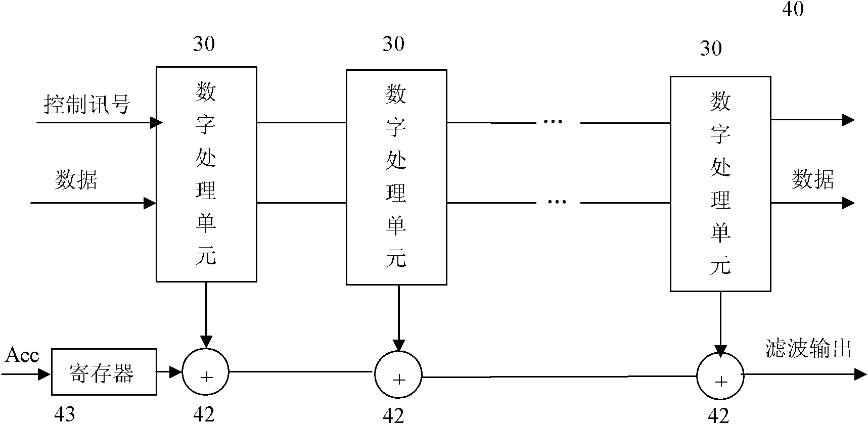
[0008] 1) When the number of filter coefficients K is large, the FIR filter in the prior art generally multiplies each filter coefficient with the data to be filtered to obtain sub-results. This process is completed in parallel, but then the sub-results are added to obtain the filtered result. When the results are obtained, the time required for the accumulation directly depends on the number of filter coefficients. When the number of filter coefficients is large, the critical path for the output of the filter results is very long, which seriously affects its work efficiency;
[0009] 2) The number of digital processing units is limited by the number of filter coefficients. Only after the number of filter coefficients in the application is determined can the number of digital processing units be fixed, which lacks application flexibility.
[0010] 3) In one-dimensional filtering applications, there is a principle of locality in the data to be filtered. Loading repeated data makes the use efficiency of the data to be filtered very low. In addition, repeated access to the memory will have a large time overhead on the one hand, and on the other hand will increase the power consumption of the system

Method used


Image

  • Finite impulse response (FIR) filter
  • Finite impulse response (FIR) filter
  • Finite impulse response (FIR) filter

Examples


Embodiment Construction

[0040] In order to make the object, technical solution and advantages of the present invention clearer, the present invention will be described in further detail below in conjunction with specific embodiments and with reference to the accompanying drawings. While illustrations of parameters including particular values ​​may be provided herein, it should be understood that parameters need not be exactly equal to the corresponding values, but rather may approximate the values ​​within acceptable error margins or design constraints.

[0041] The applicant found that the algorithm of the FIR filter in Equation 1 can be expanded to the following result:

[0042]

[0043] For the expansion results of the FIR filter algorithm shown above, the use of filter coefficients has the following rules:

[0044](1) With regard to the column where each dotted line box is located, each multiplier uses a filter coefficient and BS data to be filtered in the dotted line box to perform calculatio...


PUM


Abstract

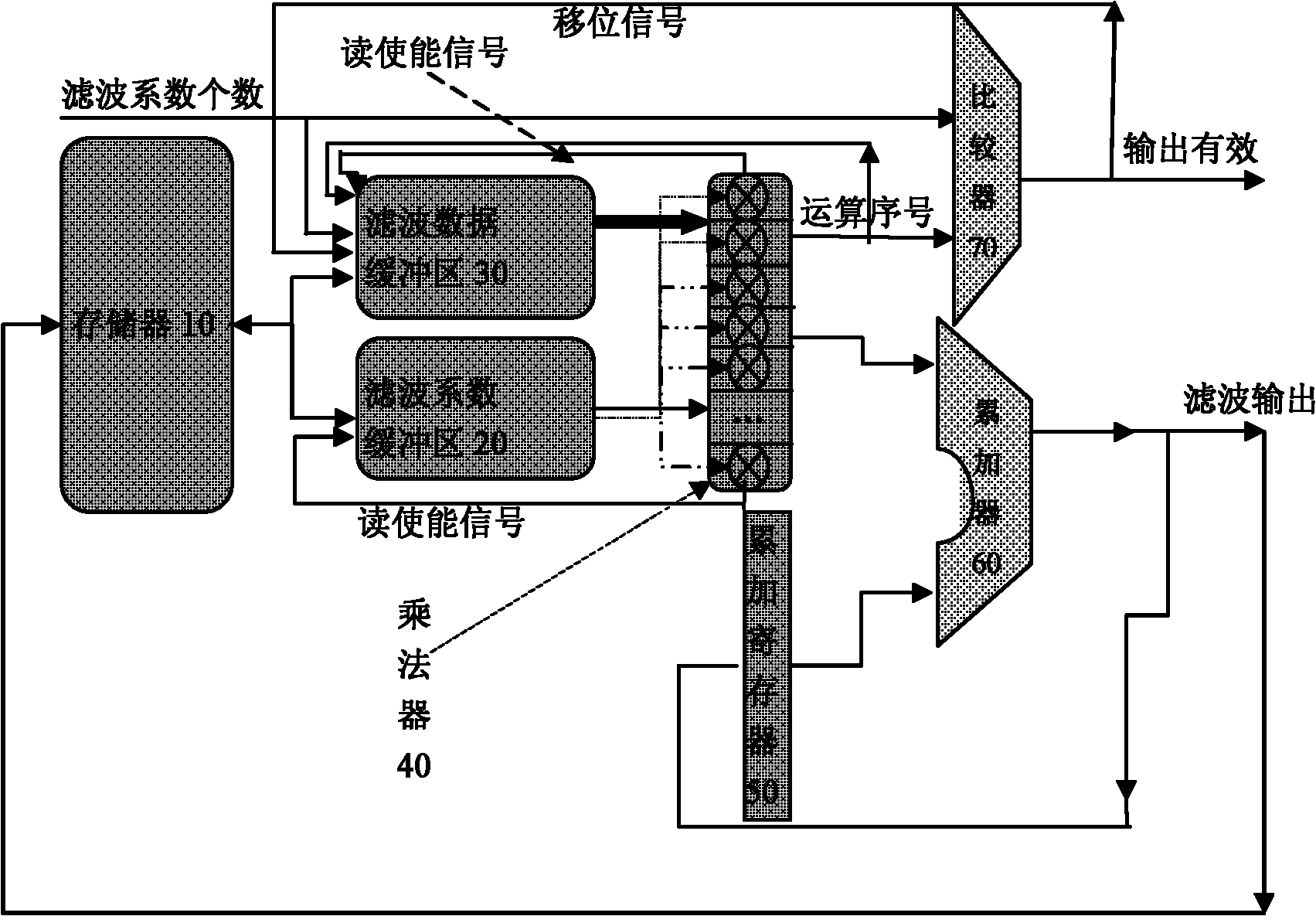
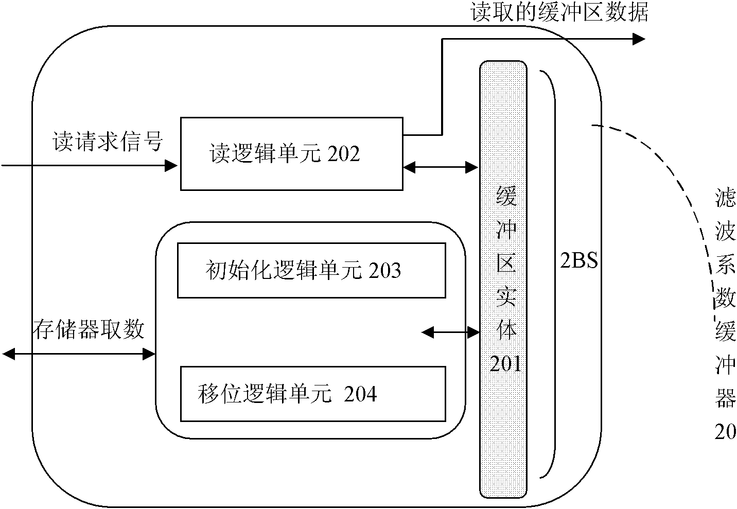
The invention discloses a finite impulse response (FIR) filter, which consists of a filtering coefficient buffer, a to-be-filtered data buffer, a multiplier, an accumulator, an accumulating register and a comparator, wherein the filtering coefficient buffer is used for buffering coefficients which are used in the filter; the to-be-filtered data buffer is used for buffering data to be filtered; the multiplier is used for computing a product of a single filter coefficient multiplied by BS data to be filtered; the accumulator is used for computing a sum of the output of the multiplier and the output of the accumulating register; the accumulating register is used for storing a result of the accumulator; and the output of the comparator is used for indicating whether the current output of the accumulator is filtering output. By adoption of the FIR filter, high efficiency of parallel computation can be realized.

Description

technical field [0001] The invention relates to the technical field of digital signal processing in the electronics industry, in particular to a finite impulse response (Finite Impulse Response, FIR for short) filter based on a multiply-accumulator. Background technique [0002] FIR filters are widely used in digital communication systems, and the industry has been working on improving their filtering performance. This filter can be used to perform various tasks such as matched filtering, noise isolation, channel equalization, etc. [0003] In general, the FIR filter algorithm can be expressed as: [0004] Y → ( k ) = Σ i = 0 K - 1 H → ( i ) X ...

Claims


Application Information

Patent Timeline
IPC IPC(8): H03H17/02
Inventor 王东琳尹磊祖谢少林汪涛张志伟
Owner BEIJING SMART LOGIC TECH CO LTD
Learn More