Implementation method of H-type groove fractal UC-EBG (Uniplanar Compact Electromagnetic Band Gap) structure oriented to multifrequency antenna substrate

A technology of UC-EBG and its implementation method, which is applied to antennas, printed circuit parts, electrical components, etc., can solve the problems of large unit size, limited application, and little research on multi-band characteristics, so as to achieve easy processing and improve utilization rate , Realize the effect of moving the bandgap to low frequency

Inactive Publication Date: 2012-06-20
BEIJING UNIV OF POSTS & TELECOMM
View PDF3 Cites 18 Cited by
  • Summary
  • Abstract
  • Description
  • Claims
  • Application Information

AI Technical Summary

Problems solved by technology

[0015] At present, there are very few studies on the properties of the electromagnetic bandgap structure AMC and its multi-band characteristics at home and abroad.
Especially for the low frequency band design of multi-band electromagnetic bandgap structure is almost no
Due to the long wavelength corresponding to the low frequency band, the unit size of the general EBG structure is large, which limits its practical application
Therefore, it is a big challenge to design a miniaturized multi-band UC-EBG structure

Method used


Image

  • Implementation method of H-type groove fractal UC-EBG (Uniplanar Compact Electromagnetic Band Gap) structure oriented to multifrequency antenna substrate
  • Implementation method of H-type groove fractal UC-EBG (Uniplanar Compact Electromagnetic Band Gap) structure oriented to multifrequency antenna substrate
  • Implementation method of H-type groove fractal UC-EBG (Uniplanar Compact Electromagnetic Band Gap) structure oriented to multifrequency antenna substrate

Examples


Embodiment Construction

[0049] To further illustrate the substantive characteristics and remarkable progress of the present invention through the following specific embodiments:

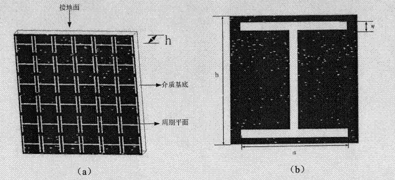
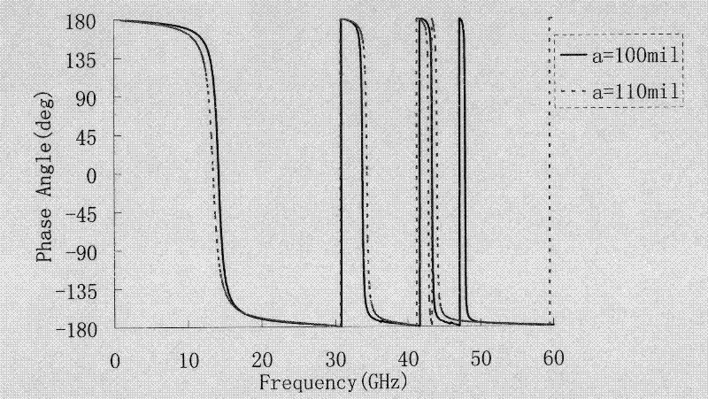
[0050] First, choose to design the UC-EBG structure in the high-frequency band where it is easier to realize multi-band. The specific implementation method is: introduce the surface slotting technology in antenna design into the design of multi-band UC-EBG. Based on the relative permittivity of ε = 10.2, the thickness of h = 25mil on the RT / Duroid 6010, the periodic unit patch is opened with H-shaped grooves such as figure 1 As shown in (b), it is called H-groove UC-EBG structure. Preliminarily set the length of the H-shaped groove as a=100mil, the width as w=8mil, the size of the period unit b=120mil, and four band gaps appear below the frequency below 60GHz.

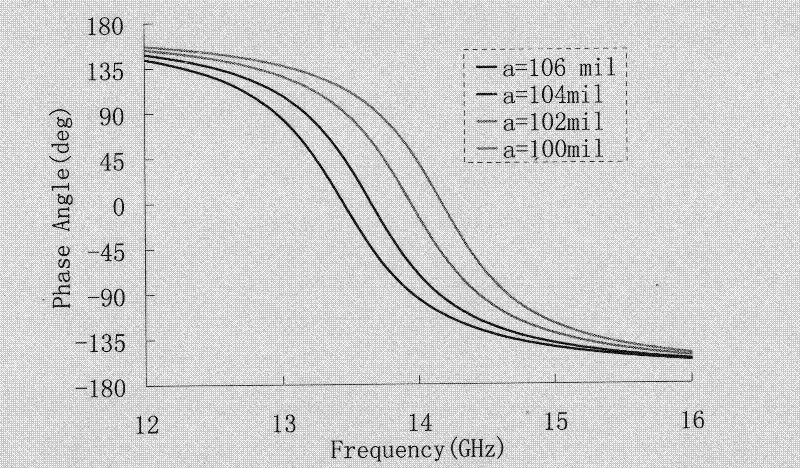
[0051] Second, the effects of the length a, width w, the dielectric constant ε of the dielectric substrate, and the scaling factor SF of the periodic unit on the b...


PUM


Abstract

The invention relates to an implementation method of a multi-frequency-band UC-EBG (Uniplanar Compact Electromagnetic Band Gap) structure and belongs to the technical field of electromagnetic propagation and reception. According to the method provided by the invention, an H-type groove is arranged on a unit paster, so as to design a four-frequency-band H-type groove UC-EBG structure within a frequency range of less than 60GHz; the invention also provides a method for realizing the miniaturization of the structure by increasing the groove length w of the H-type groove, decreasing the groove width a and increasing the dielectric constant epsilon of a dielectric substrate and the like. In addition, the method provided by the invention can be used for further realizing the miniaturization of the EBG structure by introducing an H-type groove primary fractal structure, and designing the four-frequency-band H-type groove UC-EBG structure within a frequency range of less than 3 GHz by enlarging the structure through the period unit size SF (Scale Factor). The implementation method provided by the invention can be used for solving the problem that the EBG structure has less possibility of realizing multiple frequency bands in a lower frequency because of the size restriction and providing guidance for the specific design of a multi-frequency-band miniaturized electromagnetic band-gap structure.

Description

technical field [0001] The invention is a realization method of designing a multi-band novel electromagnetic bandgap structure by engraving H-shaped grooves on UC-EBG structural period unit patches and introducing a first-order fractal structure, belonging to the technical field of electromagnetic transmission and reception. Background technique [0002] 1. The concept of EBG structure and its bandgap formation mechanism [0003] Photonic crystals are periodic dielectric materials with frequency band gaps. They were first proposed in the field of optics, and later expanded to microwave and millimeter wave bands. They are called microwave photonic crystals or electromagnetic band gaps, referred to as EBG structures. The EBG structure has unique electromagnetic wave propagation characteristics, and can be formed by periodic arrangement of metal, dielectric, ferromagnetic or ferroelectric materials implanted in dielectric materials, which has aroused great interest. [0004] T...

Claims


Application Information

Patent Timeline
Patent Type & Authority Applications(China)
IPC IPC(8): H05K1/02H01Q15/14
Inventor 田慧平赵腊梅刘凌宇纪越峰
Owner BEIJING UNIV OF POSTS & TELECOMM
Why Eureka
Try Eureka