Refrigeration cycle device

A circulation device and refrigerant technology, applied in the direction of gas cycle refrigerators, irreversible cycle compressors, reversible cycle compressors, etc., can solve the problems of unstable rotation of expanders, achieve stable rotation, and prevent over-expansion Effect

Active Publication Date: 2012-06-20
MITSUBISHI ELECTRIC CORP
View PDF5 Cites 6 Cited by
  • Summary
  • Abstract
  • Description
  • Claims
  • Application Information

AI Technical Summary

Problems solved by technology

However, the on-off valve closes after detecting the activation of the second compressor, and the rotation of the second compressor and the expander may become unstable until the discharge pressure of the expander reaches an appropriate expansion pressure after the activation of the second compressor. question

Method used


Image

  • Refrigeration cycle device
  • Refrigeration cycle device
  • Refrigeration cycle device

Examples


no. 1 approach

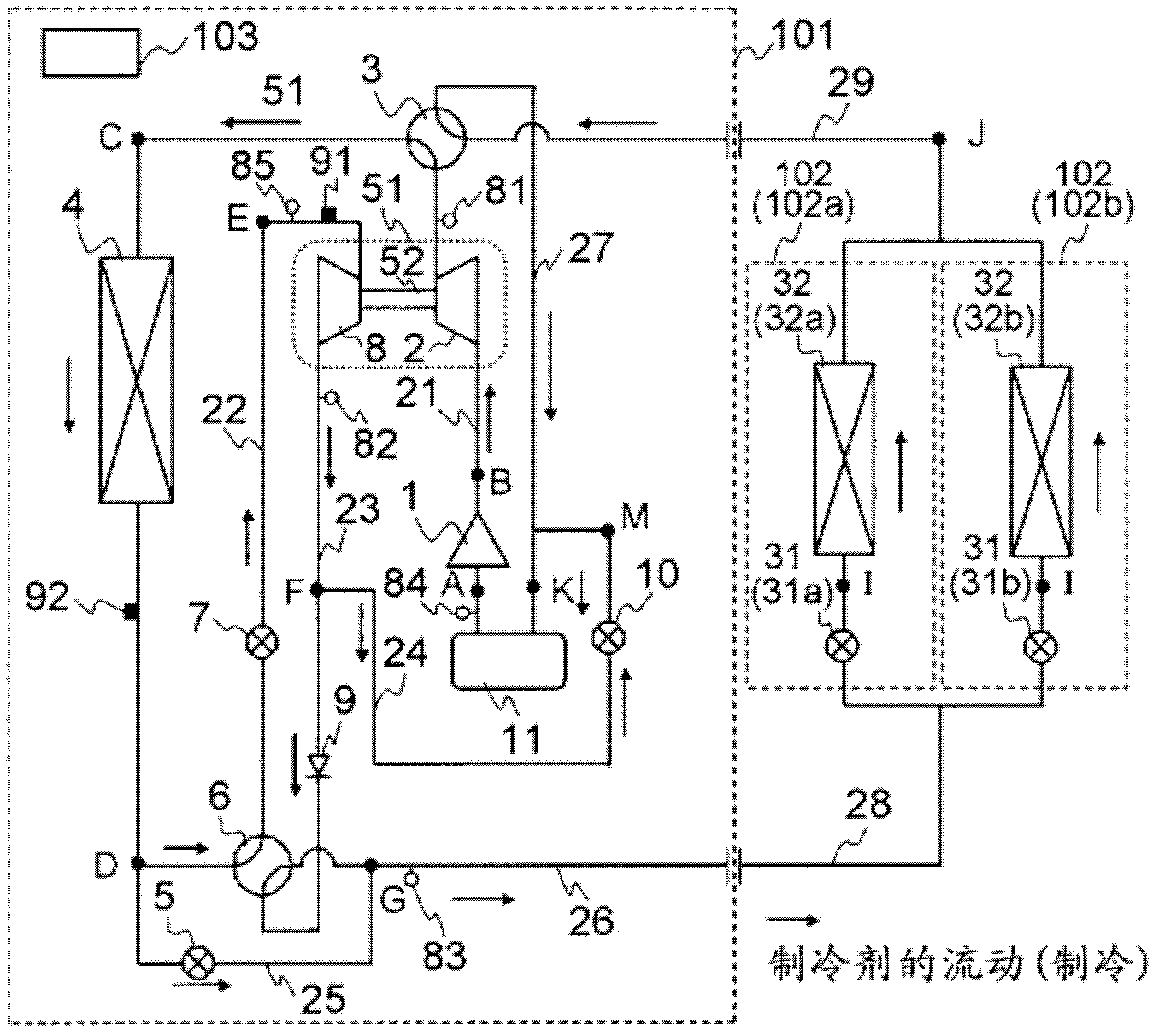
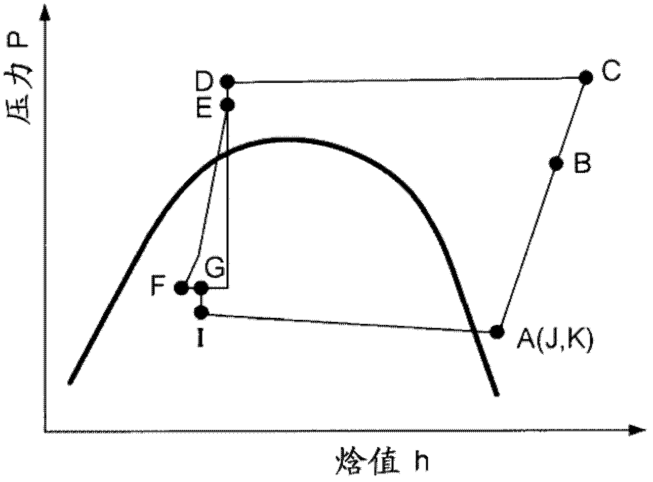
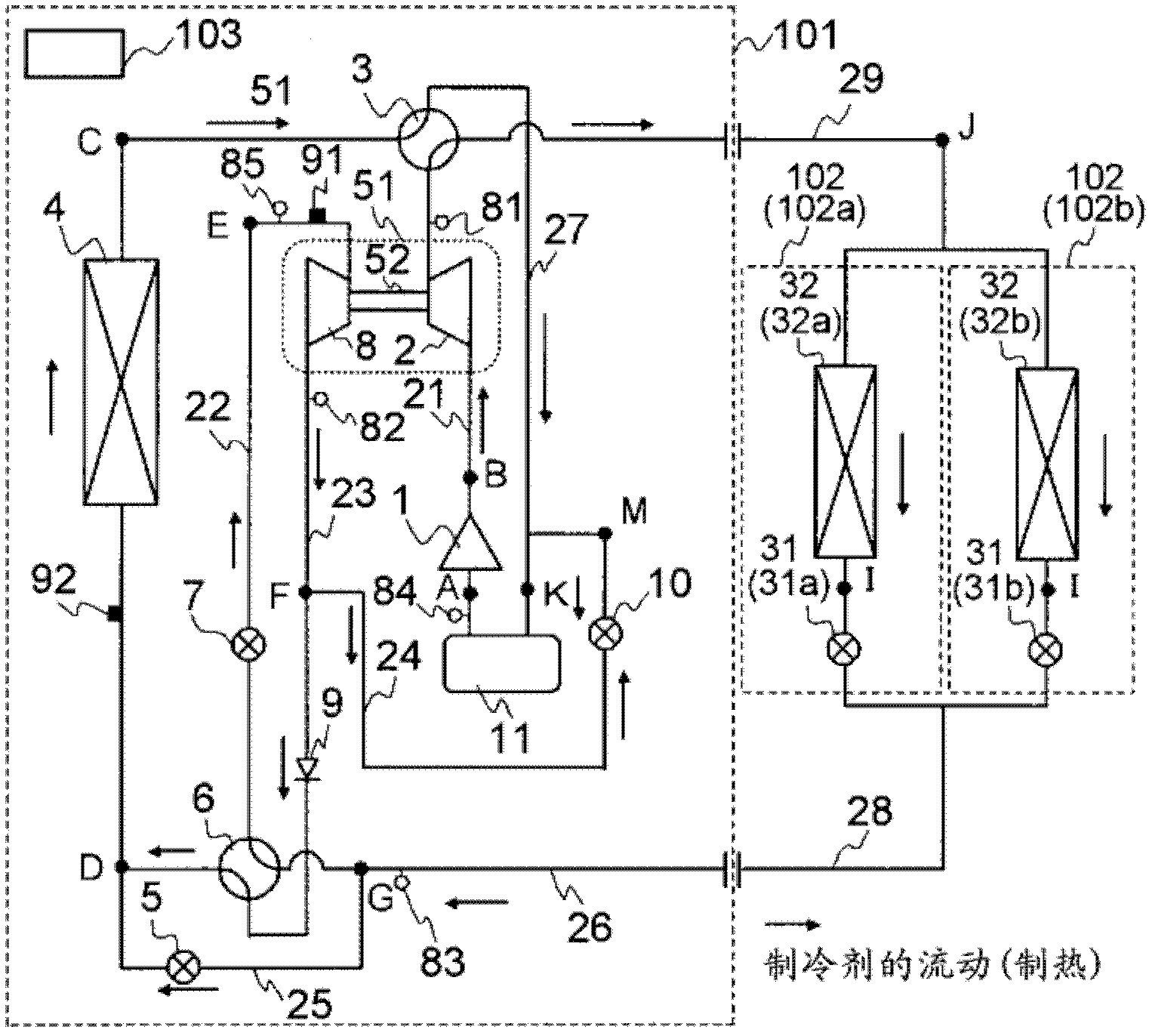
[0031] figure 1 It is a refrigerant circuit diagram at the time of cooling operation of the air conditioner equipped with the refrigeration cycle apparatus concerning 1st Embodiment of this invention. figure 2 yes figure 1 Refrigerant circuit diagram of the air conditioner in cooling operation.

[0032] figure 1 The air conditioner has a refrigerating cycle device, and the refrigerating cycle device is sequentially connected to the first compressor driven by the motor and compressing the refrigerant, the second compressor, and the outdoor heat exchanger 4 through piping, so that the refrigerant passing through the interior is expanded and transferred from the refrigerant An expander 8 for recovering power and an indoor heat exchanger 32 . The second compressor 2 and the expander 8 are connected through the drive shaft 52 , the power is recovered by the expander 8 , and the power is used to drive the second compressor 2 through the drive shaft 52 .

[0033] The outdoor ...

no. 2 approach

[0143] The first embodiment described above is designed to prevent the expander 8 from becoming over-expanded during operation. The second embodiment is designed to prevent the expander 8 from becoming overexpanded when the air conditioner is started.

[0144] Figure 15 It is a flowchart showing the operation of preventing overexpansion of the expander 8 according to the second embodiment of the present invention. in addition, Figure 16 It is a graph showing a change in high pressure and a change in discharge pressure of an expander when the air conditioner is started. exist Figure 16 In , the dotted line indicates the case where the operation for preventing the overexpansion of the expander 8 is not performed. exist Figure 16 In the figure, the solid line represents the case where the action to prevent the over-expansion of the expander 8 is performed, that is, the Figure 15 The control situation shown. Here, in the description Figure 15 before the flowchart of ...

no. 3 approach

[0156] In the above-described first and second embodiments, the refrigerant discharged from the first compressor 1 is directly sucked into the second compressor 2 . In the third embodiment, the refrigerant discharged from the first compressor 1 is sucked into the second compressor 2 after being cooled by the intercooler 4 a. In addition, as an action to prevent overexpansion of the expander 8 Figure 11 and Figure 15 In terms of the control shown, the third embodiment is the same as the first embodiment and the second embodiment.

[0157] Figure 17 It is a refrigerant circuit diagram during cooling operation of the air conditioner of the third embodiment. A refrigerant heat exchanger 14 is provided for bypassing the refrigerant from the discharge pipe 23 of the expander 8 to the inlet pipe of the accumulator 11 (refrigerant returned to the first compressor 1 through the first bypass valve 10 ). ) exchanges heat with the refrigerant (refrigerant bypassed from the main rad...


PUM


Abstract

A refrigeration cycle device is provided with: a refrigeration cycle formed by sequentially connecting by means of piping a first compressor (1), a heat dissipater, an expander (8) for expanding a refrigerant which has passed through the heat dissipater and recovering power from the refrigerant, and an evaporator; bypass piping (24) having one end connected to the discharge piping of the expander and the other end connected to the suction piping of the first compressor; a pressure sensor (85) and a temperature sensor (91) for respectively detecting the suction pressure and the suction temperature of the expander (8) as the physical quantities of the refrigerant sucked by the expander (8); a bypass valve (10) provided to the bypass piping (24) and regulating the flow rate of the refrigerant; and a control device (103) for controlling the extent of opening of the bypass valve (10). The control device (103) determines the appropriate discharge pressure of the expander (8) on the basis of the suction pressure and the suction temperature of the expander and opens the bypass valve (10) when the pressure at which the expander (8) discharges the refrigerant is higher than the determined appropriate discharge pressure.

Description

technical field [0001] The present invention relates to a refrigeration cycle apparatus using a refrigerant such as a fluid in a supercritical state, and more particularly to a refrigeration cycle apparatus having an expander for power recovery of fluid energy during expansion. Background technique [0002] Conventionally, as a refrigerating cycle device having an expander for power recovery of fluid energy in the expansion process, the following refrigerating cycle device includes, for example, a first compressor that compresses a refrigerant driven by an electric motor; A radiator for dissipating the heat of the above-mentioned refrigerant compressed by the machine; an expander for decompressing the above-mentioned refrigerant passing through the above-mentioned radiator; an evaporator for evaporating the above-mentioned refrigerant depressurized by the above-mentioned expander; The expansion power recovered by the expander drives a second compressor whose discharge side i...

Claims


Application Information

Patent Timeline
Patent Type & Authority Applications(China)
IPC IPC(8): F25B1/10F25B1/00F25B11/02
CPCF25B13/00F25B2313/02742F25B2500/26F25B11/02F25B1/10F25B2600/2501F25B2400/14F25B2309/061F25B1/00F25B43/006F25B2400/0409F25B2400/16F25B2700/19F25B2700/191
Inventor 高山启辅岛津裕辅角田昌之永田英彰鸠村杰
Owner MITSUBISHI ELECTRIC CORP
Why Eureka
Try Eureka