
Positioning processing method of cylinder member with large slenderness ratio

A processing method and technology of slenderness ratio, applied in metal processing equipment, manufacturing tools, auxiliary devices, etc., can solve the problems of difficult control of deformation of slender parts and insufficient processing accuracy, so as to save the work of alignment and adjustment Quantity, low manufacturing cost, and improved work efficiency

Inactive Publication Date: 2014-08-20
SHANGHAI XINLI MACHINE PLANT
View PDF6 Cites 0 Cited by
  • Summary
  • Abstract
  • Description
  • Claims
  • Application Information

AI Technical Summary

Problems solved by technology

[0008] The problem to be solved by the present invention is to overcome the problem that the above-mentioned existing processing technology is difficult to control the deformation of the slender parts, resulting in the problem that the processing accuracy cannot meet the technical requirements

Method used


Image

  • Positioning processing method of cylinder member with large slenderness ratio
  • Positioning processing method of cylinder member with large slenderness ratio

Examples


Embodiment 1

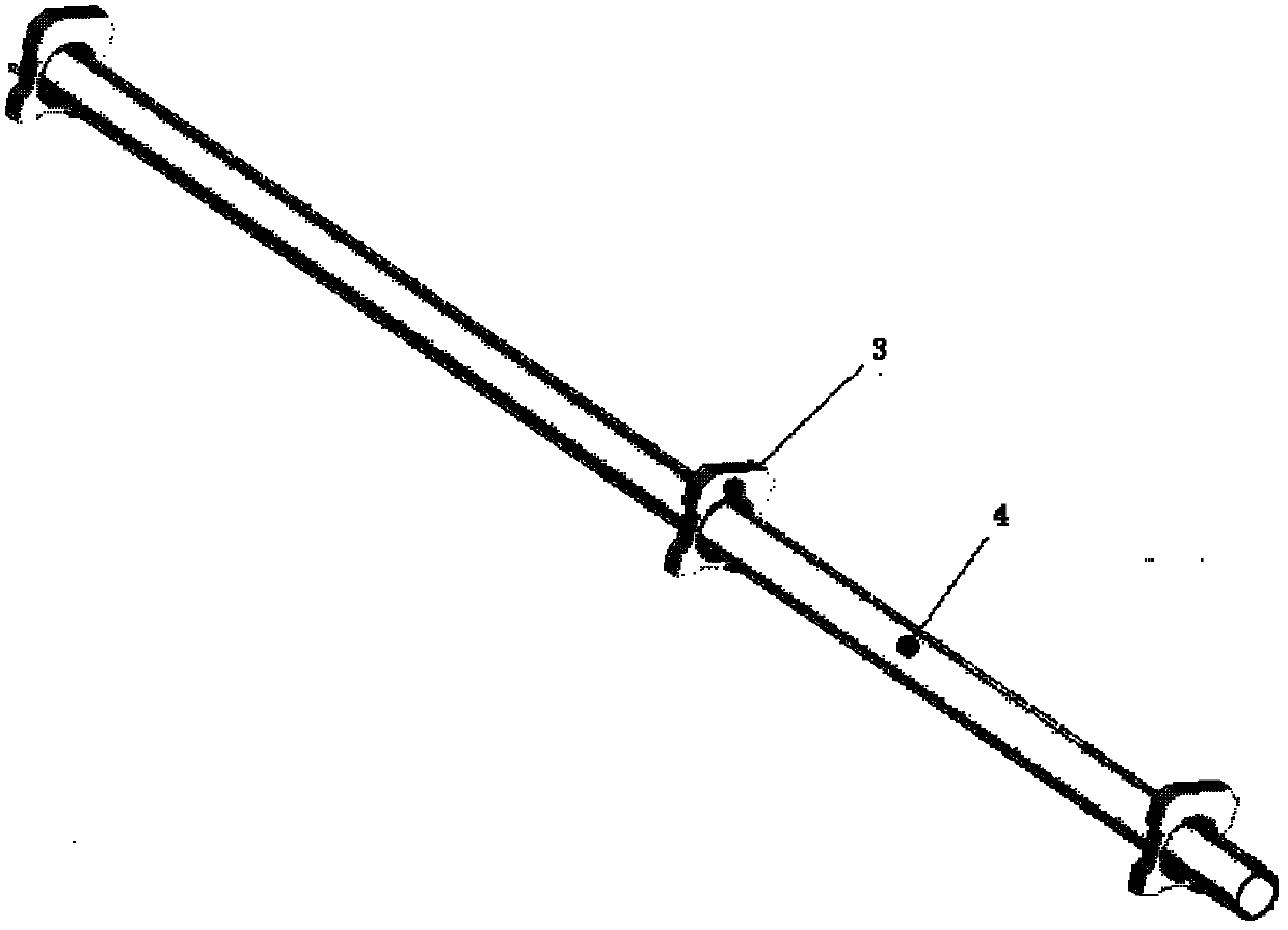
[0040] The cylinder has a length of 4500 mm, an outer diameter of 108 mm, and a wall thickness of 4 mm. The diameter of the support rod is 10mm and the length is 4600mm. The design requirements of the components are: three support rods are fixed on the outer surface of the cylinder by spot welding.

[0041] First, control the dimensional accuracy of the outer circle of the cylinder and the support rod. After the support rod is fitted on the outer surface of the cylinder (that is, tangent), the first two solder joints are fixed. After the first fixation, the cylinder and the support rod are fixed. The mutual position of the axes is established. The second fixed point fits the two outer circles according to the method of the first fixed point, and the vertical direction (Y direction) ± in the radial direction (the line connecting the center of the cylinder and the support rod through the tangent point) of the first fixed point Implement the second two solder joints within 0.5 ...

Embodiment 2

[0043] After the first support rod is fixed on the outer surface of the cylinder, the latter two processes—fixed welding of the second support rod and the third support rod—begin to be implemented. Before each process thereafter, the 120° space position between the support rod of this process and the first support rod must be found. In addition, it is also necessary to control the axial corresponding positions of every two welding spots at the 48 fixing positions and the two welding spots at the fixing position of the first support rod, so as to ensure the axial position requirements of the welding spots of the 48 groups of components. Therefore, the workload of alignment and adjustment is very large and difficult, and the reliability of the process is also low, so it is difficult to guarantee product quality.


PUM


Abstract

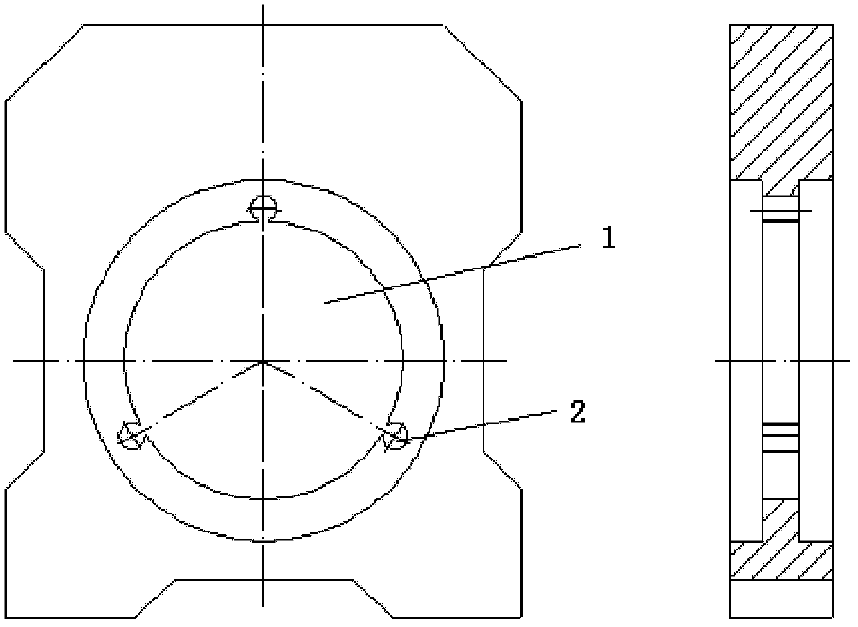
The invention relates to a positioning processing method of a cylinder member with large slenderness ratio, which involves a cylinder and a positioning bracket as a process device. The method comprises distributing an axial through hole on the bracket to determine the aperture size and the outer diameter fit clearance of the cylinder; uniformly distributing three through holes with a diameter of 10mm on the outer edge of the axial through hole of the bracket, wherein the three small holes are externally tangent to the through hole of the bracket; cutting off 2mm from two sides of a connection line of tangent points along the axial direction of the small hole to form a rectangular cavity; marking the direction of the positioning bracket; and limiting relative radial positions of the cylinder and a supporting rod. With the process method, deformation of the cylinder and the supporting rod is overcome and then welding fixation is performed for eliminating error caused by the deformation. The method of the invention is simple and effective, efficient and practical, resolves the problem of technical orientation of the member with large slenderness ratio and breaks through a production key limit, so that intricate regulation of the relative position sizes of two components constituting the member is obviated, reliable size control is achieved and the quality is reliably ensured.

Description

technical field [0001] The invention relates to the technical field of cylindrical member processing, in particular to a positioning processing method for a super-slender cylindrical member. Background technique [0002] The meaning of super slender ratio cylinder member is: the ratio of the maximum dimension of the cross section of the member (also called radial direction) to the longitudinal dimension of the member (also called axial direction). A component with a slenderness ratio greater than 1:15 is called a slender member, and a component with a slenderness ratio greater than 1:35 is an ultra-slender cylindrical component. The technical requirements of existing components are: [0003] 1. The three support rods form a 120-degree space angle in the outer garden of the cylinder (also known as uniform distribution); [0004] 2. After the support rod is fixed on the outer surface of the cylinder, the parallelism between the axis of the support rod and the axis of the cyl...

Claims


Application Information

Patent Timeline
Patent Type & Authority Patents(China)
IPC IPC(8): B23K37/04
Inventor 虞春波张国华陈超群谢勤卫潘伟民
Owner SHANGHAI XINLI MACHINE PLANT
Learn More