Compact high-rigidity layout structure of dry cutting gear hobber

A technology of dry cutting and layout structure, which is applied in the field of gear hobbing machines, can solve the problems of difficult design of fast chip removal structure, large space occupied by the whole machine, unsuitable layout structure, etc., to achieve compact structure, small space occupation of cutting area, and occupation of small space effect

Inactive Publication Date: 2012-06-27
CHONGQING MACHINE TOOL GROUP
View PDF7 Cites 6 Cited by
  • Summary
  • Abstract
  • Description
  • Claims
  • Application Information

AI Technical Summary

Problems solved by technology

At the same time, the distance between the large column and the rear column is relatively wide, the whole machine takes up a large space and the layout is relatively loose
In addition, the large column and the rear column are arranged separately, the working area is relatively large, it is not easy to close, and the design of the fast chip removal structure is very difficult, and the layout structure is not suitable for dry chip processing

Method used


Image

  • Compact high-rigidity layout structure of dry cutting gear hobber
  • Compact high-rigidity layout structure of dry cutting gear hobber
  • Compact high-rigidity layout structure of dry cutting gear hobber

Examples


Embodiment Construction

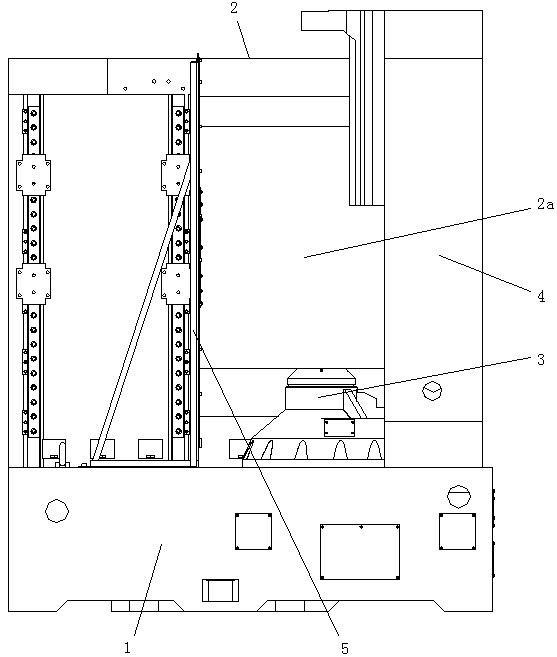
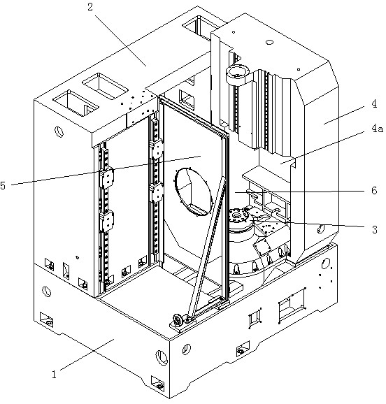
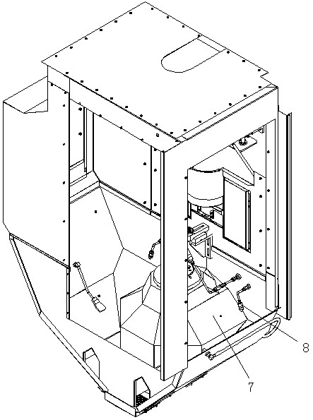
[0018] figure 1 It is the front view of the layout structure of the compact high rigidity dry cutting gear hobbing machine of the present invention; figure 2 A three-dimensional view of the layout structure of this compact high-rigidity dry cutting gear hobbing machine; image 3 It is a schematic diagram of the three-dimensional structure of the cutting shield; Figure 4 A three-dimensional view of the layout structure of this compact high-rigidity dry cutting gear hobbing machine with a chip guard.

[0019] As shown in the figure, the layout structure of the compact high-rigidity dry cutting gear hobbing machine in this embodiment includes a bed 1, a large column 2, a workbench 3 and a rear column 4, and the large column 2 is arranged on the longitudinal side of the bed 1 Above, the rear column 4 is arranged on the lateral side of the bed 1, the ends of the large column 2 and the rear column 4 are connected to form an L-shaped structure, and the middle part of the bed is a...


PUM


Abstract

The invention discloses a compact high-rigidity layout structure of a dry cutting gear hobber, which comprises a body, a large vertical column, a worktable and a rear vertical column. The large vertical column is arranged on a longitudinal edge of the body, the rear vertical column is arranged on a transverse edge of the body, an end of the large vertical column is connected with an end of the rear vertical column to form an L-shaped structure, an isolation baffle plate is further arranged in the middle of the body, and the worktable is arranged between the isolation baffle plate and the rear vertical column on the body. The large vertical column and the rear vertical column are fixedly connected with each other to achieve high rigidity, the sizes of the large vertical column and the rear vertical column can be reduced, the large vertical column and the rear vertical column are in L-shaped arrangement to achieve compact structure, a cutting area occupies small space, and the overall size of the gear hobber with the layout structure is small. A chip protecting cover is arranged on the inner wall of the cutting area, high-temperature scrap iron can be prevented from contacting with a machine tool body, and chips can be rapidly discharged out of the cutting area, so that heat transferred to the machine tool body by the scrap iron is decreased, the temperature of a machine tool can be decreased, and precision of the machine tool is ensured. Therefore, the layout structure is applicable to the dry cutting gear hobber.

Description

technical field [0001] The invention relates to a gear hobbing machine, in particular to a layout structure of a gear hobbing machine. Background technique [0002] The main structure of the machine tool of the traditional gear hobbing machine includes: the bed, the large column, the workbench and the rear column. Located on the central axis of the bed. In this layout structure, the large column and the rear column are independently connected to the bed, and there is no connection between the large column and the rear column. Therefore, the volume of the large column and the rear column must be made larger to ensure their rigidity. At the same time, the distance between the large column and the rear column is relatively wide, the whole machine takes up a large space, and the layout is relatively loose. In addition, the large column and the rear column are arranged separately, the working area is relatively large, and it is not easy to be closed. The design of the fast chip...

Claims


Application Information

Patent Timeline
Patent Type & Authority Applications(China)
IPC IPC(8): B23Q1/01B23Q11/08B23F23/00
CPCB23F5/22B23F17/003Y02P70/10
Inventor 陈鹏李先广黄强
Owner CHONGQING MACHINE TOOL GROUP
Why Eureka
Try Eureka