
Electric braking control system against mistakenly stepping on accelerator during braking

A technology of stepping on the accelerator by mistake and braking control, applied in the field of electronic brake control system for stepping on the accelerator by mistake, can solve the problems of increasing the signal input PLC time, prolonging the time for the system to respond to braking, prolonging the scanning period, etc., to eliminate the safety hidden worries, shorten the scanning cycle, improve the effect of security

Inactive Publication Date: 2012-06-27
张连民
View PDF8 Cites 0 Cited by
  • Summary
  • Abstract
  • Description
  • Claims
  • Application Information

AI Technical Summary

Problems solved by technology

[0003] However, there are still imperfections in the above-mentioned system in use:
[0004] (1) The electrical signal generated by the pressure sensor is an analog quantity. The analog electrical signal must be processed by a special function module before the PLC can recognize it. This requires adding a function module, thereby increasing the time for the signal to be input to the PLC. At the same time, the display shows The content must also be supported by the communication of the PLC, which inevitably prolongs the scan cycle of the PLC, thereby prolonging the time for the entire system to respond to braking
[0005] (2) The switch button must be switched manually by the driver and passengers, and the structure is cumbersome. Once this operation is missed, there is still a huge hidden danger when the vehicle overtakes and suddenly steps on the accelerator.

Method used


Image

  • Electric braking control system against mistakenly stepping on accelerator during braking
  • Electric braking control system against mistakenly stepping on accelerator during braking

Examples


Embodiment Construction

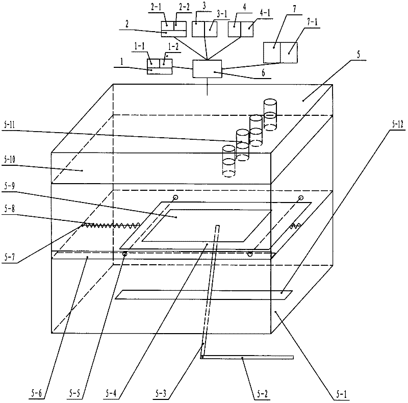
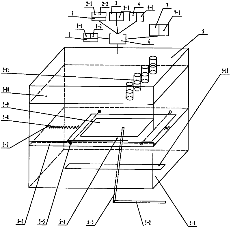
[0019] Referring to the accompanying drawings, the braking control system of accidentally stepping on the accelerator:

[0020] A braking control system (1), which mainly executes the braking command output by the PLC (6) by the relay (1-1) and the solenoid valve (1-2), and acts on the original braking system of the vehicle, and is used for braking the vehicle When stepping on the accelerator by mistake, the acceleration changes to braking instantaneously;

[0021] A fuel supply control system (2), which mainly executes the commands output by the PLC (6) by the relay (2-1) and the solenoid valve (2-2), and acts on the original fuel supply system of the vehicle, and is used for braking and accidentally stepping on the accelerator , quickly reduce the engine speed of the vehicle;

[0022] A warning device (3), mainly a voice alarm (3-1), used to remind the vehicle that the accelerator pedal movement speed has reached a critical state from normal speed to abnormal speed;

[002...


PUM


Abstract

The invention discloses an electric braking control system against mistakenly stepping on an accelerator during braking. The electric braking control system comprises a braking control system against mistakenly stepping on the accelerator during braking and a protection device, wherein the braking control system against mistakenly stepping on the accelerator during braking comprises a braking control system, an oil supply control system, a warning device, a preparation device, a car accelerator pedal movement speed signal generator and a PLC (Programmable Logic Controller). When the accelerator of a car is abnormally stepped on, acceleration can be changed into braking automatically and instantly; and since a digital quantity signal generated by the car accelerator pedal movement speed signal generator in real time can be directly recognized by the PLC, the speed of the overall system in response to braking is ensured to be higher. The protection device is used for providing a signal to the PLC when the car overtakes and accelerates normally, the PLC automatically blocks possible error output at the time, so that the potential safety hazard brought by missing of additional operations is eliminated; when the car drives normally, the PLC unblocks the output blockage automatically, so that the system performs normally to ensure that driving of the car is safer.

Description

technical field [0001] The invention relates to an electronic brake control system for accidentally stepping on the accelerator by braking. Background technique [0002] On August 3, 2011, the State Intellectual Property Office published an invention case with the publication number CN102139641A. This case discloses a switchable brake and accelerator control system, which consists of a brake and accelerator intelligent control system and a solenoid valve. Its intelligent control system is mainly composed of display screen, braking system, PLC, accelerator signal generator and pressure sensor. The accelerator signal generator and pressure sensor convert the pressure on the accelerator pedal of the vehicle into an electrical signal. This signal is controlled by the PLC. Compared with the set parameters, when the signal is abnormal, the PLC outputs instructions, the PLC instruction execution device and the original braking system of the vehicle realize the vehicle braking; the ...

Claims


Application Information

Patent Timeline
IPC IPC(8): B60W50/14B60W10/18B60W10/06B60W30/02
Inventor 张连民
Owner 张连民
Learn More