Elevator tractor

A technology of elevator traction machine and traction wheel, which is applied to elevators, electrical components, electromechanical devices, etc. in buildings, and can solve the problems of high brake performance requirements, small braking torque, lifting, etc., and improve the overall transmission efficiency , reduce performance requirements, and reduce manufacturing costs

Inactive Publication Date: 2012-06-27
HITACHI ELEVATOR CHINA
View PDF8 Cites 3 Cited by
  • Summary
  • Abstract
  • Description
  • Claims
  • Application Information

AI Technical Summary

Problems solved by technology

The traction machine is mainly composed of a permanent magnet synchronous motor, a traction wheel and a braking device. This traction machine is braked at the end of the traction wheel. Due to the self-locking nature of the worm, a large braking torque must be directly applied to the shaft end of the traction wheel; It has the characteristics of simple structure, reliable operation, small size, light weight, high efficiency, low speed and large torque, but the main component of permanent magnets is rare earth materials. In recent years, with the increasing price of rare earth resources, the cost of magnetic steel has increased rapidly Correspondingly, the cost of the traction machine continues to rise, and the economic benefits become lower, especially for the traction machine with high rated torque that requires more magnets, the cost is further increased. The performance requirements are also relatively high, which also increases the cost of the traction machine to a certain extent
[0004] The second type is asynchronous geared traction machine, its structure mainly includes AC asynchronous motor, worm gear or helical gear reduction mechanism, brake and traction wheel, the power of AC asynchronous motor is transmitted to the traction wheel through the reduction mechanism, brake and asynchronous The motor is separated and coaxially fixedly connected, and the brake is on the motor side. Its characteristics are that the required braking torque is small and the performance requirements of the brake are low. This kind of traction machine has a simple structure and mature technology. It is currently mostly used in low-speed elevators. And freight elevators, but because the traction machine adopts asynchronous motor and deceleration mechanism at the same time, and adopts split design in structure, it has low motor efficiency, large volume, low transmission efficiency, high energy consumption, high noise, and poor ride comfort And other issues
Some of the asynchronous geared traction machines also use a helical gear reduction mechanism, which improves the overall transmission efficiency of the traction machine to a certain extent. However, due to the use of asynchronous motors, the working speed of the helical gears is high, resulting in serious wear and low life. , greater noise, etc., especially the large volume of the machine room increases the volume of the elevator machine room used to place the traction machine, wasting a lot of construction space and building materials, and cannot meet the current needs of people for small machine room elevator products

Method used


Image

  • Elevator tractor
  • Elevator tractor
  • Elevator tractor

Examples


Embodiment 1

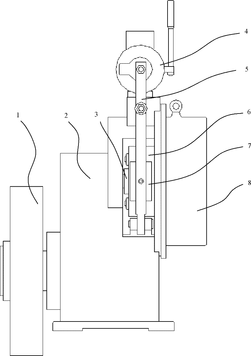
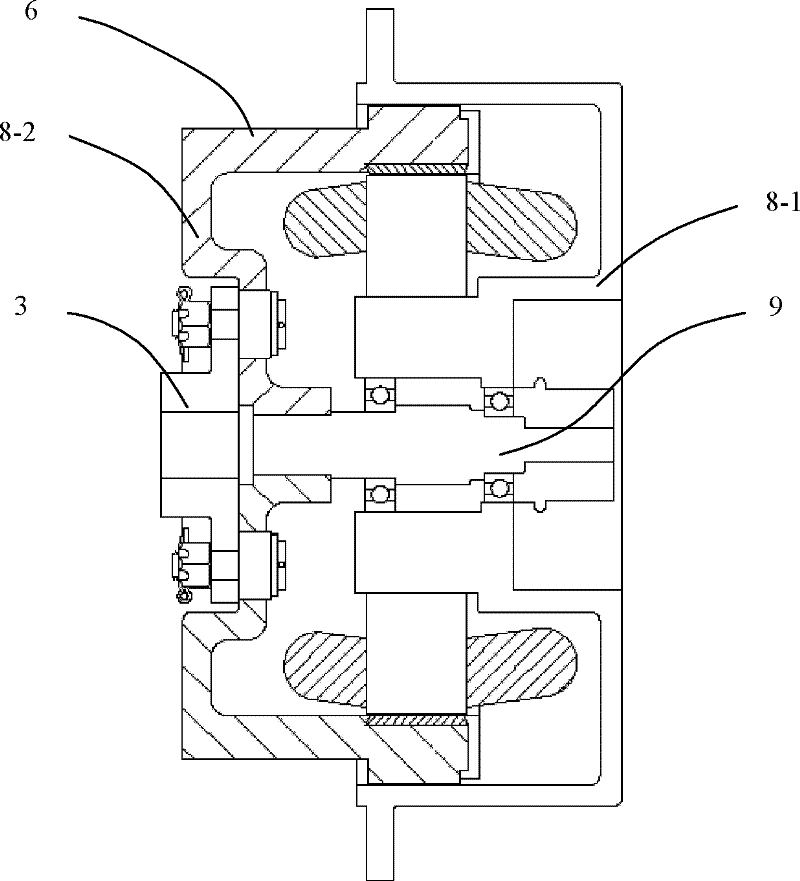
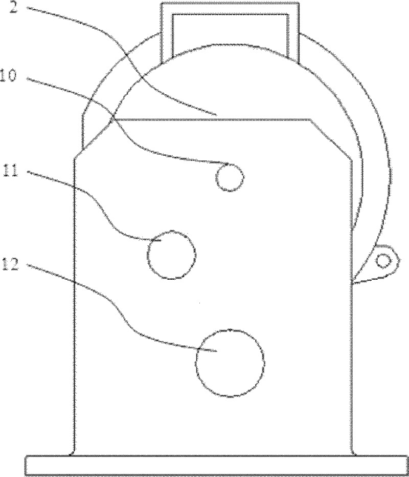
[0025] see Figure 1 to Figure 4 , the elevator traction machine described in the present invention includes a synchronous motor 8, a reduction box 2, a traction wheel and an electromagnetic brake 4, wherein the electromagnetic brake 4 includes a brake wheel 6 and a brake shoe 7 that cooperate with each other for braking, so The synchronous motor 8 includes a motor body 8-1 and an outer rotor 8-2, the brake wheel 6 is integrated on the outer rotor 8-2, the outer rotor 8-2 and the brake wheel 6 are located between the motor body 8-1 and the deceleration Between the boxes 2, the outer rotor 8-2 of the synchronous motor 8 is a part of the coupling 3, the input shaft 10 of the reduction box 2 is connected with the main shaft 9 of the synchronous motor through the coupling 3, and the output shaft 10 of the reduction box 2 It is concentrically connected with the main shaft of the traction wheel 1. In this embodiment, the reduction box 2 is a two-stage reduction structure, including ...

Embodiment 2

[0030] see Figure 5 The difference between this embodiment and Embodiment 1 is that the reduction box 2 of the elevator traction machine of this embodiment is a one-stage reduction structure, and the end of the input shaft 10 is provided with a worm 13, and the worm 13 passes through the corresponding The meshed worm wheel 14 is connected to the output shaft 12 which is concentrically connected to the main shaft of the traction sheave 1 .

[0031] Based on the above structure, after the synchronous motor 8 is energized and started, the rotation of the synchronous motor main shaft drives the reduction box input shaft 10 connected with it to rotate synchronously, and the input shaft 10 drives the worm gear 14 through the worm 13 arranged at its end, and the worm gear 14 The traction sheave 1 is driven to rotate through the output shaft 12 and the main shaft of the traction sheave. Through the above transmission process, the synchronous motor 8 finally transmits its power to the...


PUM


Abstract

The invention relates to an elevator tractor which comprises a synchronous motor, a speed reducing box, a traction wheel and an electromagnetic brake, wherein the electromagnetic brake comprises a brake wheel and a brake shoe which are matched with each other for braking; the synchronous motor comprises a main motor body and an outer rotor; and the brake wheel is integrated on the outer rotor and is positioned between the main motor body of the synchronous motor and the speed reducing box. Compared with an asynchronous geared tractor, the elevator tractor can work at lower rotating speed and is lower in noise; a helical gear is adopted by the elevator tractor in a matching way and is taken as a speed reducing mechanism of a transmission part, so that the whole transmission efficiency of the elevator tractor can be improved; the speed reducing box is arranged, so that the requirement on the output torque of the synchronous motor can be reduced, the cost increase of an elevator caused by the facts that larger moment is output by the synchronous motor and a great deal of magnetic steel is needed to be used is avoided; an input end of the speed reducing box is braked, so that the braking moment is small, and the requirement on the brake is low; and meanwhile, by adopting a structure integrating a brake disc, a coupler and the outer rotor of the motor, the elevator tractor is compact in structure and meets the using requirement of a small machine room elevator.

Description

technical field [0001] The invention relates to an elevator traction machine used in a vertical elevator driving system, belonging to the technical field of lifting facilities. Background technique [0002] The existing elevator traction machine mainly has the following two structural types: [0003] One is the permanent magnet synchronous gearless traction machine, which is also the most widely used elevator traction machine at present. Its characteristic is that the permanent magnet synchronous motor directly drives the traction sheave to rotate without a deceleration mechanism. The traction machine is mainly composed of a permanent magnet synchronous motor, a traction wheel and a braking device. This traction machine is braked at the end of the traction wheel. Due to the self-locking nature of the worm, a large braking torque must be directly applied to the shaft end of the traction wheel; It has the characteristics of simple structure, reliable operation, small size, l...

Claims


Application Information

Patent Timeline
Patent Type & Authority Applications(China)
IPC IPC(8): B66B11/04H02K7/116
Inventor 鲁国雄闫涛王泽伟
Owner HITACHI ELEVATOR CHINA
Why Eureka
Try Eureka