Soil-retaining dam and construction method thereof

A technology for dam body and waste tires, which is applied in the direction of filling, dam, wall dam, etc., can solve the problems of secondary pollution, etc., and achieve the effects of stable structure, fast processing speed and strong impact resistance

Inactive Publication Date: 2012-06-27
NORTH CHINA UNIV OF WATER RESOURCES & ELECTRIC POWER
View PDF6 Cites 7 Cited by
  • Summary
  • Abstract
  • Description
  • Claims
  • Application Information

AI Technical Summary

Problems solved by technology

The burning of waste tires will cau

Method used


Image

  • Soil-retaining dam and construction method thereof
  • Soil-retaining dam and construction method thereof
  • Soil-retaining dam and construction method thereof

Examples


Embodiment 1

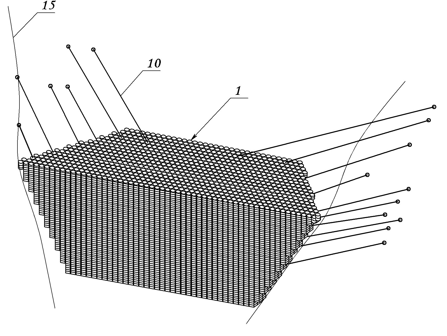
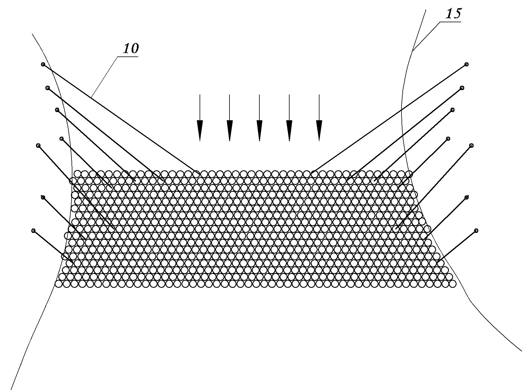
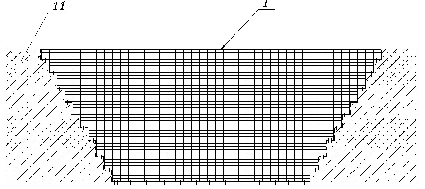
[0054] Embodiment one: see figure 1 , Figure 4 and Figure 5 , the dam body of the integral check dam is composed of multiple layers of the waste tire prestressed mesh vertically stacked. A group of waste tires on the same vertical line of the dam body penetrates vertically parallel steel strands vertically, and the two ends of the steel strands are respectively fixed on the outer surfaces of the upper and lower tires after prestressing; the inside of the dam body Nodes are set on the prestressed steel strands, and steel cables are distributed and fixed on each node. Each steel cable is pulled upstream along the countercurrent direction and fixed in the rock formation or on the slopes of the two banks.

[0055] Each layer of waste tire prestressed mesh is a network structure formed by sequentially butt jointing of a plurality of waste tire prestressed belts in the longitudinal direction, and longitudinally parallel steel strands 3 are inserted into the longitudinally adjace...

Embodiment 2

[0060] Embodiment 2: the accompanying drawings are not drawn, the content is basically the same as that of Embodiment 1, the similarities will not be repeated, the difference is: the two ends of the steel strand are respectively fixed with bolts, and the bolts cooperate with the nuts to fix the steel strand On the side spacers on the outer edge of the outermost tire.

Embodiment 3

[0061] Embodiment three: the accompanying drawings are not drawn, and the content is basically the same as that of embodiment one, and the similarities will not be repeated. The difference is: the opposite sides of the waste tire prestressed mesh are provided with conjoined gaskets, that is The ends of each steel strand are fixed on the same conjoined spacer, and the through hole at the intersection of the steel strand and the conjoined spacer is a bar-shaped hole, so as to facilitate the adjustment of the prestress of the steel strand in different directions.


PUM


Abstract

The invention discloses a soil-retaining dam which is formed by combining waste tyres, and a construction method thereof. A dam body is formed by stacking a plurality of layers of waste tyre prestressed mesh sheets; each of the waste tyre prestressed mesh sheets is formed by combining a plurality of waste tyre prestressed belts; each of the waste tyre prestressed belts is formed when parallel steel stranded wires pass through each waste tyre; two ends of each of the steel stranded wires are fixed on the outer edges of the outmost tyres of two ends respectively after each of the steel stranded wires applies prestress to each waste tyre; nodes are arranged on the prestressed steel stranded wires on the inner side of the dam body; a steel rope is fixedly arranged on each node; and each steel rope is pulled towards the upstream of a channel obliquely along a counter current direction and is fixed at a dam slope of a dam foundation. Through the soil-retaining dam and the construction method thereof, wastes can be recycled in low cost; the soil-retaining dam is suitable to be processed on site quickly so as to meet the requirements in emergencies, is high in strength and impact resistance, has a stable structure, cannot be loose and is durable in use; the dam body is high in self-supporting strength; and the self weight and stability of the soil-retaining dam can be improved by filling concrete, stone materials, sand and stones which are silted up naturally and the like manually in gaps among the waste tyres.

Description

technical field [0001] The invention relates to a dam structure in the field of water conservancy and hydropower engineering, in particular to a check dam formed by using waste tire assemblies and a construction method for the check dam. Background technique [0002] Check dam is a dam structure built for the purpose of retaining mud and silt in ditches at all levels of water and soil erosion. It is an important measure for comprehensive management of small watersheds. Prevention and control of water and soil erosion, flood detention, mud retention, and silt, raising the base level of gully erosion, and improving local production and living conditions. Warping dams mainly built with local materials have the problems of long construction period, large amount of materials and high construction cost. [0003] Waste tires account for a considerable proportion of industrial solid waste, and the recycling and utilization of waste tires has attracted more and more attention. With...

Claims


Application Information

Patent Timeline
IPC IPC(8): E02B7/08E02D17/18
Inventor 刘尚蔚魏鲁双赵京晖张国新李胜机郑茗元刘凤莲魏群
Owner NORTH CHINA UNIV OF WATER RESOURCES & ELECTRIC POWER
Why Eureka
Try Eureka