Physical simulation visualization experimental device and forming method thereof
An experimental device and physical simulation technology, which is applied in the fields of earthwork drilling, measurement, wellbore/well components, etc., can solve the problems of difficult to achieve reservoir pressure, difficult to simulate thin oil reservoirs with 3D visualization model, and impossible to achieve. broad effect
- Summary
- Abstract
- Description
- Claims
- Application Information
AI Technical Summary
Problems solved by technology
Method used
Image

Examples
Embodiment approach 1
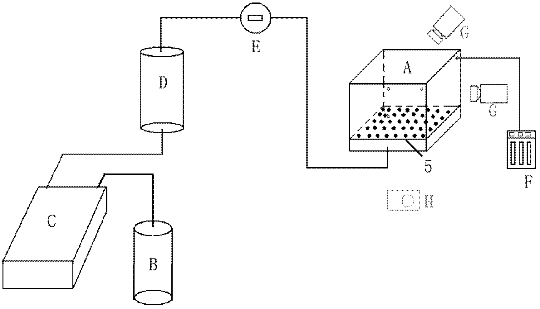
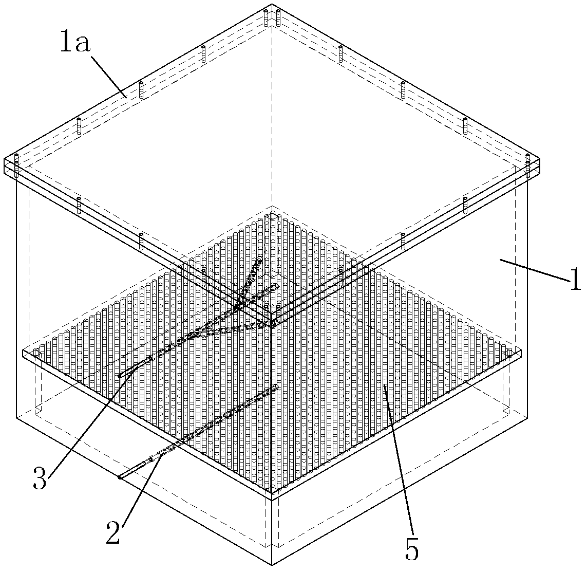
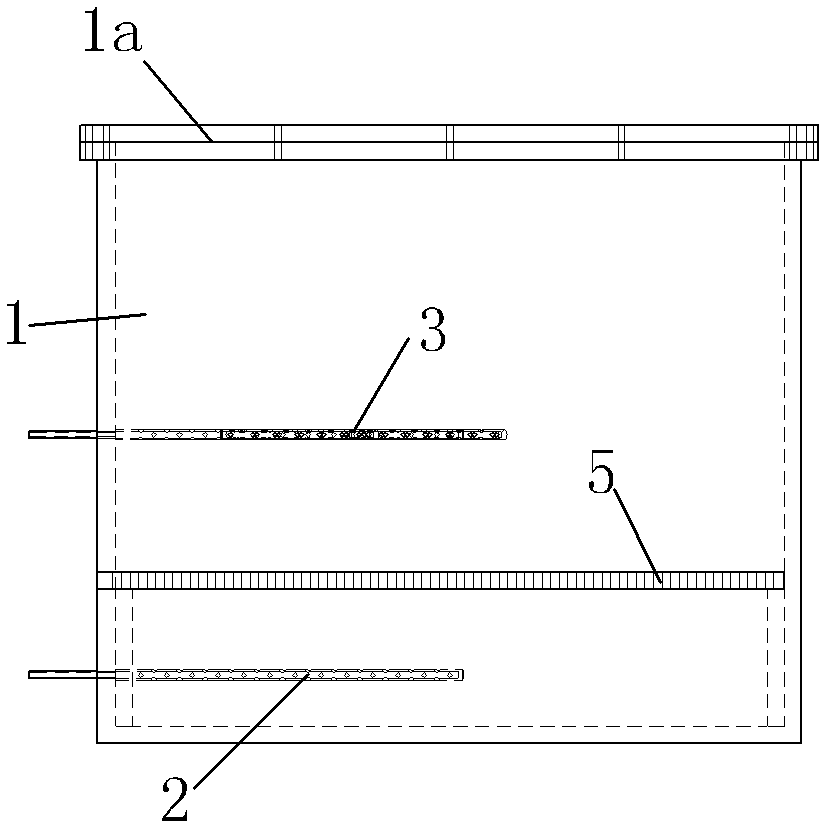
[0066] The embodiment of the present invention proposes a physical simulation visualization experiment device A, which includes a box body 1 , a water injection well 2 and a horizontal production well 3 . The box body 1 is a cube with a top cover 1a on the top, and the box body 1 is filled with porous media. One end of the water injection well 2 is arranged in the box body 1, and the other end protrudes from the box body 1 to be exposed. The horizontal production well 3 is arranged horizontally, and the horizontal production well 3 includes a main shaft 3a, the tail end of the main shaft 3a is connected with a connecting shaft 3b, and the side of the main shaft 3a is provided with at least one branch shaft 3c , the branch shaft 3c is located on the horizontal plane of the main shaft 3a, the main shaft 3a and the branch shaft 3c are located inside the box 1, and the connecting shaft 3b is located outside the box 1, the A plurality of perforations 4 are uniformly arranged on th...
Embodiment approach 2
[0089] The embodiment of the present invention also proposes a method for forming a visualization experiment device, which includes the steps of:
[0090] A box body 1, a water injection well 2 and a horizontal production well 3 are formed, the horizontal production well 3 includes a main shaft 3a, the tail end of the main shaft 3a is connected with a connecting shaft 3b, and the side of the main shaft 3a is provided with at least A branch wellbore 3c, the branch wellbore 3c is located on the horizontal plane of the main wellbore 3a, and a plurality of perforations 4 are uniformly arranged on the main wellbore 3a and the branch wellbore 3c;
[0091] Put the water injection well 2 and the horizontal production well 3 into the box body 1;
[0092] Filling the porous medium into the box body 1 for compaction, the water injection well 2 and the horizontal production well 3 are covered in the porous medium;
[0093] The method of water injection is used to saturate the porous medi...
PUM
 Abstract
Description
Claims
Application Information
 - R&D
- Intellectual Property
- Life Sciences
- Materials
- Tech Scout
- Unparalleled Data Quality
- Higher Quality Content
- 60% Fewer Hallucinations
Browse by: Latest US Patents, China's latest patents, Technical Efficacy Thesaurus, Application Domain, Technology Topic, Popular Technical Reports.
© 2025 PatSnap. All rights reserved.Legal|Privacy policy|Modern Slavery Act Transparency Statement|Sitemap|About US| Contact US: help@patsnap.com