Tripping oil-return system for steam turbine for nuclear power station

A technology of oil return system and steam turbine, which is applied in the direction of detailed information of nuclear power plants, nuclear power generation, nuclear power plants, etc., and can solve problems such as malfunction, steam turbine shutdown by mistake, and lower reliability

Inactive Publication Date: 2012-06-27
中广核工程有限公司 +1
View PDF5 Cites 9 Cited by
  • Summary
  • Abstract
  • Description
  • Claims
  • Application Information

AI Technical Summary

Problems solved by technology

The trip oil return system of the steam turbine in the nuclear power plant only relies on this electronic control component. The disadvantage is that once the only electronic control component malfunctions or refuses to operate, it will cause the trip oil return system of the nuclear power plant steam turbine to malfunction or refuse to operate, which may lead to huge economic loss or serious accident
However, when the protection signal does not arrive, if one of the solenoid valves ma...

Method used


Image

  • Tripping oil-return system for steam turbine for nuclear power station
  • Tripping oil-return system for steam turbine for nuclear power station
  • Tripping oil-return system for steam turbine for nuclear power station

Examples


Embodiment Construction

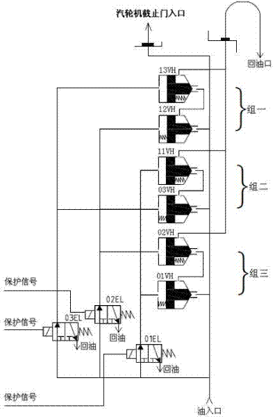
[0022] The present invention nuclear power plant steam turbine trip oil return system such as image 3 As shown, there are three groups of oil valves. Group 1 is oil valve 13VH connected in series with oil valve 12VH oil return chamber. Group 2 is oil valve 11VH connected in series with oil valve 03VH oil return chamber. Group 3 is oil valve 02VH and oil valve 01VH oil return chamber. The cavities are connected in series, and the oil return cavities between the three groups are connected in parallel.

[0023] There are three electronic control components, respectively using solenoid valves 01EL, 02EL and 03EL. The connection between the solenoid valve and the oil valve is as image 3 As shown, the solenoid valve 01EL controls the oil valve 11VH of group two and the oil valve 01VH of group three, the solenoid valve 02EL controls the oil valve 02VH of group three and the oil valve 12VH of group one, and the solenoid valve 03EL controls the oil valve 13VH and Oil valve 03VH of ...


PUM


Abstract

The invention discloses a tripping oil-return system for a steam turbine for a nuclear power station, which is used to trigger a protective system of the steam turbine to operate when a nuclear power reactor or the steam turbine breaks down so that a cut-off valve of the steam turbine protects that an oil return path returns oil rapidly to release pressure and shutdown. In the tripping oil return system for the steam turbine for the nuclear power station, three groups of oil valves are arranged. In each group, two oil return chambers of the oil valves are connected in series. The oil return chambers among the groups are connected in parallel. Three electric control assemblies are arranged. The electric control assembly I controls the oil values of the oil valve groups II and III, the electric control assembly II controls the other oil valve of the oil valve group III and one oil valve of the oil valve group I and the electric control assembly III controls the other oil valve of the oil valve group I and the other oi valve of the oil valve group II. In the invention, oil return of the oil valves is controlled by the three electric control assemblies. When two or more than two of the three electric control assemblies are in a good condition, the electric control assemblies return oil normally when receiving a protective action signal of the steam turbine. When only one electric control assembly receives the protective action signal of the steam turbine, the electric control assembly cannot return oil. Therefore, the malfunction probability can be effectively reduced and both operational safety and reliability of the steam turbine are considered.

Description

technical field [0001] The invention relates to a steam turbine trip oil return system in a nuclear power plant, which is used to trigger the action of the protection system of the steam turbine when the nuclear power reactor or the steam turbine fails, so that the oil return circuit of the protection oil circuit of the cut-off door of the steam turbine can quickly return the oil to relieve the pressure and shut down. Background technique [0002] When the nuclear power steam turbine is in normal operation, the oil flows from the oil inlet of the steam turbine to the oil supply port. When a nuclear power reactor or steam turbine fails, its protection system outputs a protection signal to the nuclear power plant steam turbine trip oil return system, and the nuclear power plant steam turbine trip oil return system controls oil flow to the oil return port, and the steam turbine no longer has oil supply and shuts down. [0003] Single-channel nuclear power plant steam turbine tr...

Claims


Application Information

Patent Timeline
IPC IPC(8): F01D21/00G21D1/00G21D3/06
CPCY02E30/40Y02E30/00
Inventor 尹刚谢俊华孙兴东李啸风张禹
Owner 中广核工程有限公司
Why Eureka
Try Eureka