Robot arm control method and control device
- Summary
- Abstract
- Description
- Claims
- Application Information
AI Technical Summary
Benefits of technology
Problems solved by technology
Method used
Image
Examples
first embodiment
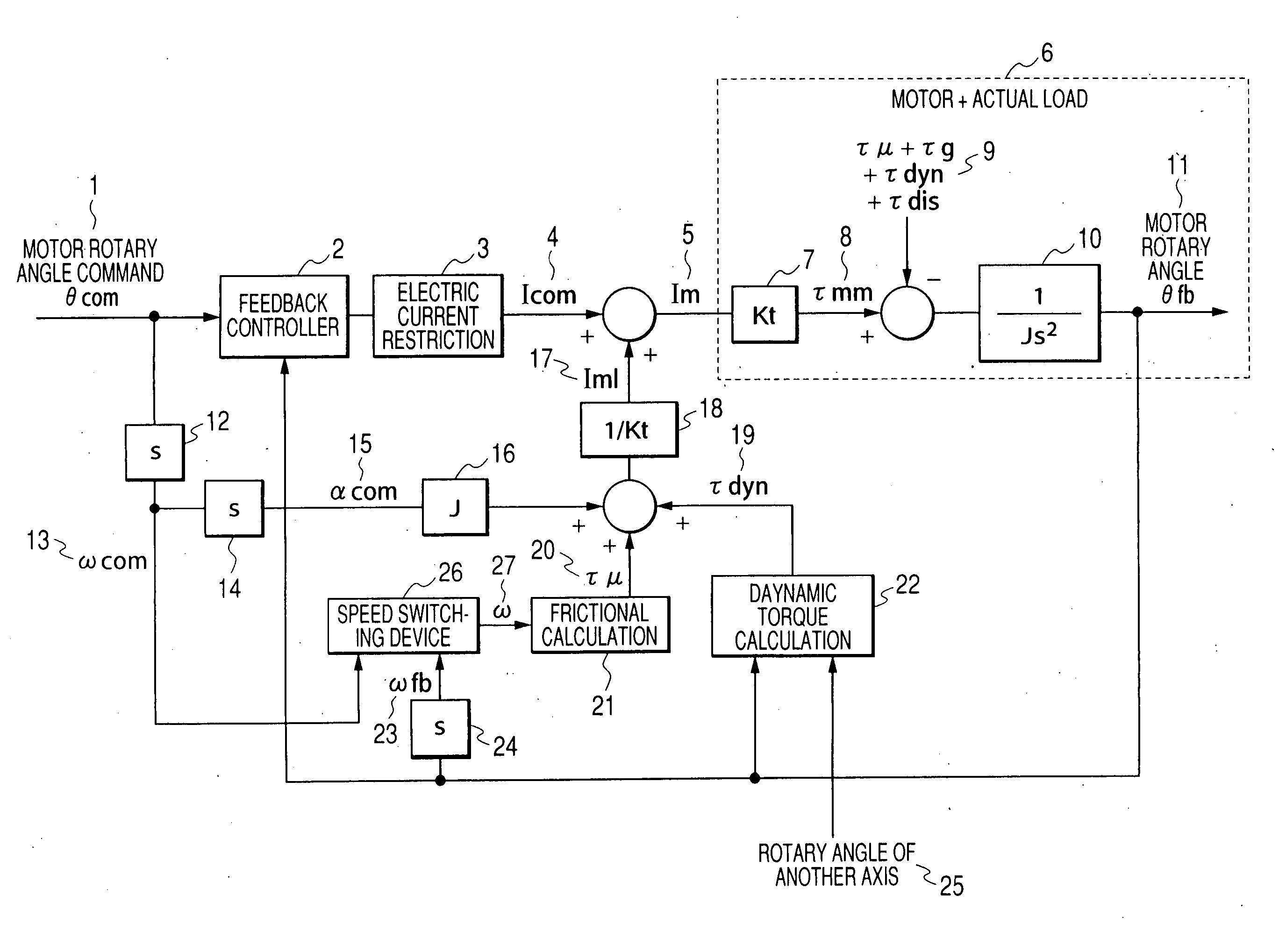
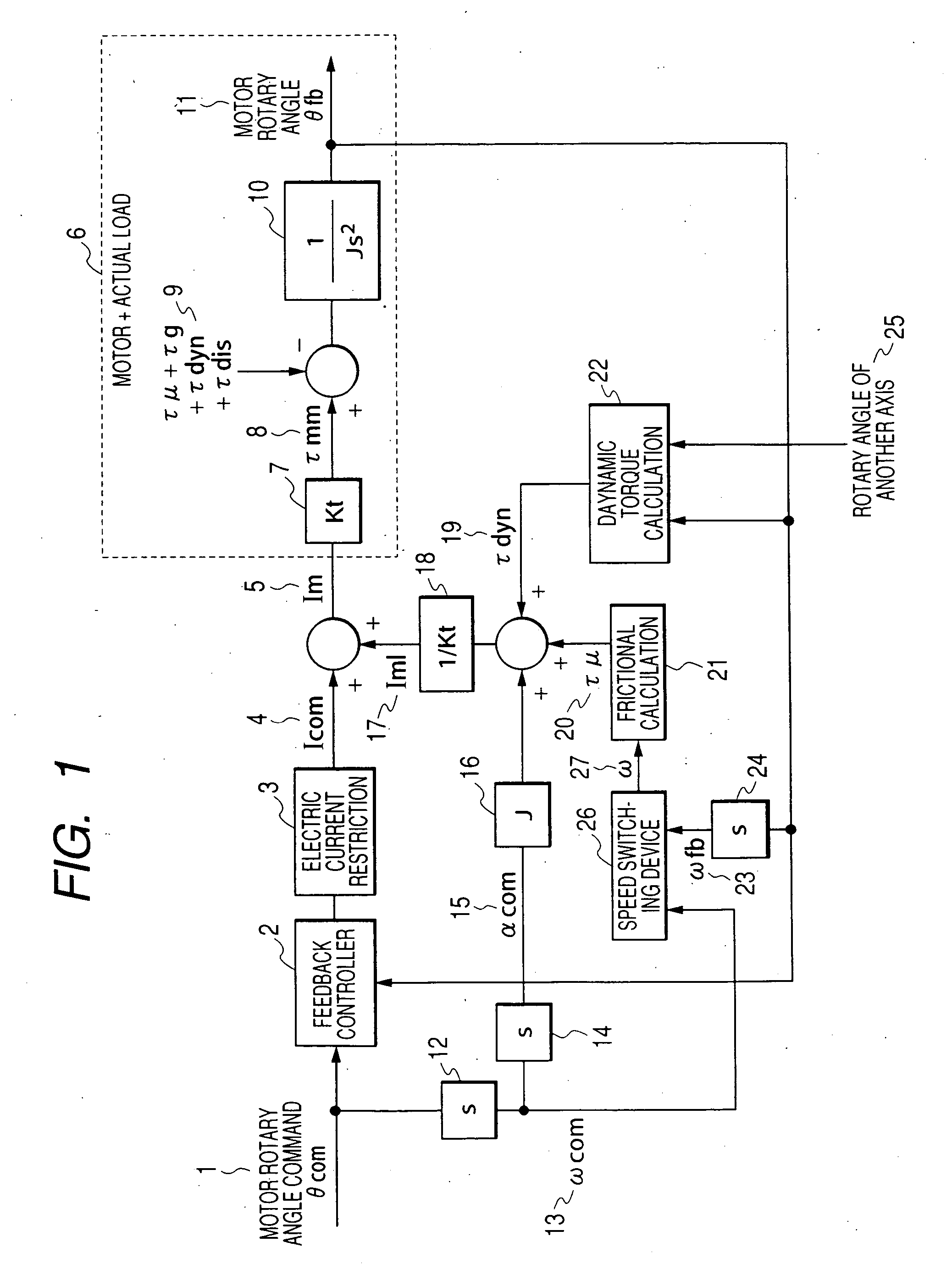
[0128]FIG. 1 is a block diagram showing the controlling method of the present invention. In FIG. 1, reference numeral 26 is a velocity switching device, and reference numeral 27 is an angular velocity ω selected by the velocity switching device. The feedback electric current command Icom (4) can be found in such a manner that PID calculation is conducted by the feedback controller (2) from the rotary angle command θcom (1) and the actual motor rotary angle θfb and that the electric current restriction (3) is conducted. Concerning the means for the electric current restriction (3), there are provided a system in which the limit is set and a system in which the feedback gain is lowered.
[0129] On the other hand, Iml (17) can be calculated by the expression (3) as follows. The angular acceleration αcom (15), which is found when the motor rotation command θcom (1) is subjected to the differential calculations (12), (14) twice, is multiplied by the motor inertia J (16). The frictional to...
second embodiment
[0138] In the expression (12) showing a switch of velocity in the first embodiment, at least one of the velocity command value and the actually measured value is multiplied by a weighting factor. ω={ω fb(kc1*ω com+kc2≤ω fb)ω com(kc1*ω com+kc2>ω fb)(13)
[0139] When the constitution is made as shown by the expression (13), priority is given to one of the velocity command value and the actually measured value so that it can be adopted as a velocity.
[0140] Since the actually measured value ωfb includes a measurement error, for example, when the weighting factor in the expression (13) is set at a value as follows, the velocity command ωcom can be preferentially selected.
kc1>1 and kc2>0 (14)
third embodiment
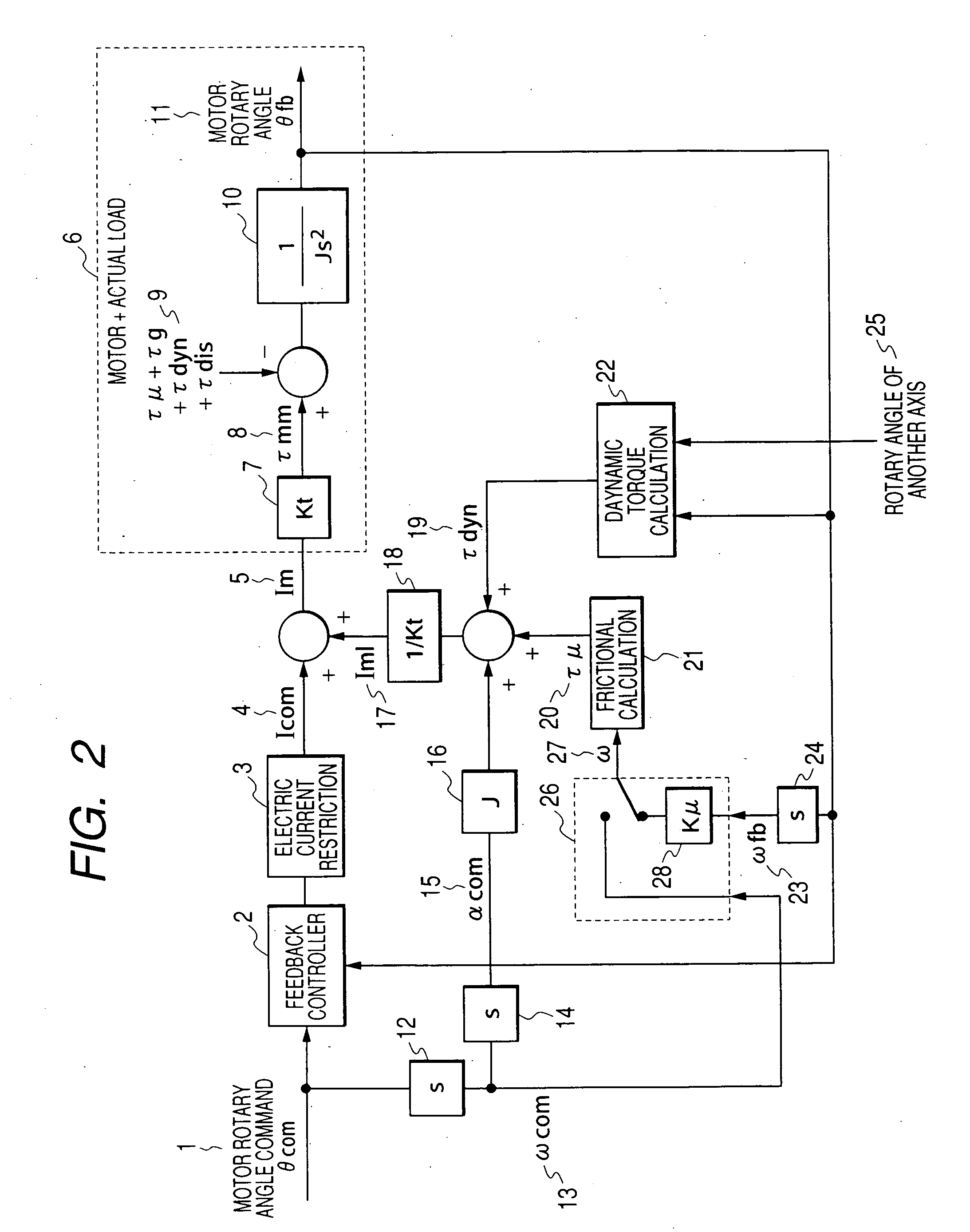
[0141]FIG. 2 is a block diagram showing a control method of the third embodiment.
[0142] The actual angular velocity ωfb (23) inputted into the velocity switching device (26) is multiplied by the frictional compensation rate kμ.
[0143] It is expressed by the expression (15) as follows. ω={k μ*ω fb(kc1*ω com+kc2≤ω fb)ω com(kc1*ω com+kc2>ω fb)(15)
[0144] kμ: Frictional compensation rate
[0145] When the angular velocity ω (27) obtained by the above expression (15) is used, in the case where the actual angular velocity ωFB (23) is selected for the angular velocity used when the frictional torque τμ (20) is calculated (21) by the expression (5), when the frictional compensation rate kμ is set at a value not more than 1, the frictional torque τμ (20) can not be compensated by 100%. Therefore, it is possible to adjust so that the feedback characteristic can not be vibrational.
[0146] On the other hand, in the case where the angular velocity command ωcom (13) is used for th...
PUM
 Abstract
Description
Claims
Application Information
 - R&D
- Intellectual Property
- Life Sciences
- Materials
- Tech Scout
- Unparalleled Data Quality
- Higher Quality Content
- 60% Fewer Hallucinations
Browse by: Latest US Patents, China's latest patents, Technical Efficacy Thesaurus, Application Domain, Technology Topic, Popular Technical Reports.
© 2025 PatSnap. All rights reserved.Legal|Privacy policy|Modern Slavery Act Transparency Statement|Sitemap|About US| Contact US: help@patsnap.com


