Control device for vehicular power transmitting apparatus

a control device and transmission device technology, applied in the direction of motor/generator/converter stopper, dynamo-electric converter control, gearing, etc., can solve the problems of shock, etc., to suppress the deterioration in the startability of the drive force source, avoid contraction, and increase the torque fluctuation

Active Publication Date: 2010-05-20
TOYOTA JIDOSHA KK
View PDF13 Cites 85 Cited by
  • Summary
  • Abstract
  • Description
  • Claims
  • Application Information

AI Technical Summary

Benefits of technology

[0043]According to the control device for the vehicular power transmitting apparatus in the first aspect, there is provided the drive-force source start control portion that switches the start modes of the drive force source depending on the vehicle condition to start the drive-force source in an appropriate method. Thus, avoidance of contraction or reduction in drive region of for instance the electric motor, suppressing a shock during start of the drive force source, and suppressing deterioration in startability of the drive force source, can be realized.
[0044]According to the control device for the vehicular power transmitting apparatus in the second aspect, further, the drive-force source start control portion selectively switches the start modes of the drive force source to the drive-force source start mode by the first and second electric motors, or the drive-force source start mode by a third electric motor. This allows an appropriate start method for the drive force source to be executed depending on the vehicle condition.
[0045]According to the control device for the vehicular power transmitting apparatus in the third aspect, the drive-force source start control portion switches the start modes of the drive force source depending on the rotation speed, torque and power of the first electric motor, to start the drive force source in an appropriate start method. In starting the drive force source by for instance the first and second electric motors, if the rotation speed of the first electric motor exceeds an allowable rotation speed, then the drive-force source start mode by the third electric motor is executed. In addition, if torque or power available to be generated by the first electric motor is lower than torque and power needed for the first electric motor to perform the drive-force source start mode, then the drive-force source start mode by the third electric motor is executed.
[0046]According to the control device for the vehicular power transmitting apparatus in the fourth aspect, the drive-force source start control portion switches the start modes of the drive force source depending on the rotation speed, torque and power of the second electric motor, to execute an appropriate start method for starting the drive force source. In starting the drive force source by for instance the first and second electric motors, if the rotation speed of the second electric motor exceeds an allowable rotation speed, then the drive-force source start mode by the third electric motor is executed. In addition, if torque or power, available to be generated by the second electric motor, is lower than torque and power needed for the second electric motor to perform the drive-force source start mode, then the drive-force source start mode by the third electric motor is executed.
[0047]According to the control device for the vehicular power transmitting apparatus in the fifth aspect, the drive-force source start control portion switches the start modes of the drive force source depending on the gear ratio of the shifting portion, to execute an appropriate start method for the drive force source depending on the gear ratio. If the drive force source is started by the first and second electric motors when the shifting portion has a large gear ratio, an increased fluctuation in torque of the second electric motor is delivered to the drive wheels to resultantly increase the shock. In such a case, starting the drive force source by the third electric motor results in a reduction in shock.
[0048]According to the control device for the vehicular power transmitting apparatus in the sixth aspect, the drive-force source start control portion switches the start modes of the drive force source depending on the shifting state of the shifting portion, to execute an appropriate start method for the drive force source depending on the shifting state. During the shifting of the shifting portion, deterioration easily occurs on controllability of the second electric motor connected to the output shaft of the differential mechanism, so that starting the drive force source by the first and second electric motors may cause deterioration in startability. In such a case, starting the drive force source by the third electric motor suppresses the occurrence of deterioration in startability.

Problems solved by technology

In the conventional start method for the drive force source, thus, not only the electric motor has the contracted drive range but also a problem arises of causing deterioration to occur in startability of the drive-force source and shocks to occur during start of the drive-force source, depending on a running condition of the vehicle.

Method used


Image

  • Control device for vehicular power transmitting apparatus
  • Control device for vehicular power transmitting apparatus
  • Control device for vehicular power transmitting apparatus

Examples


embodiment 1

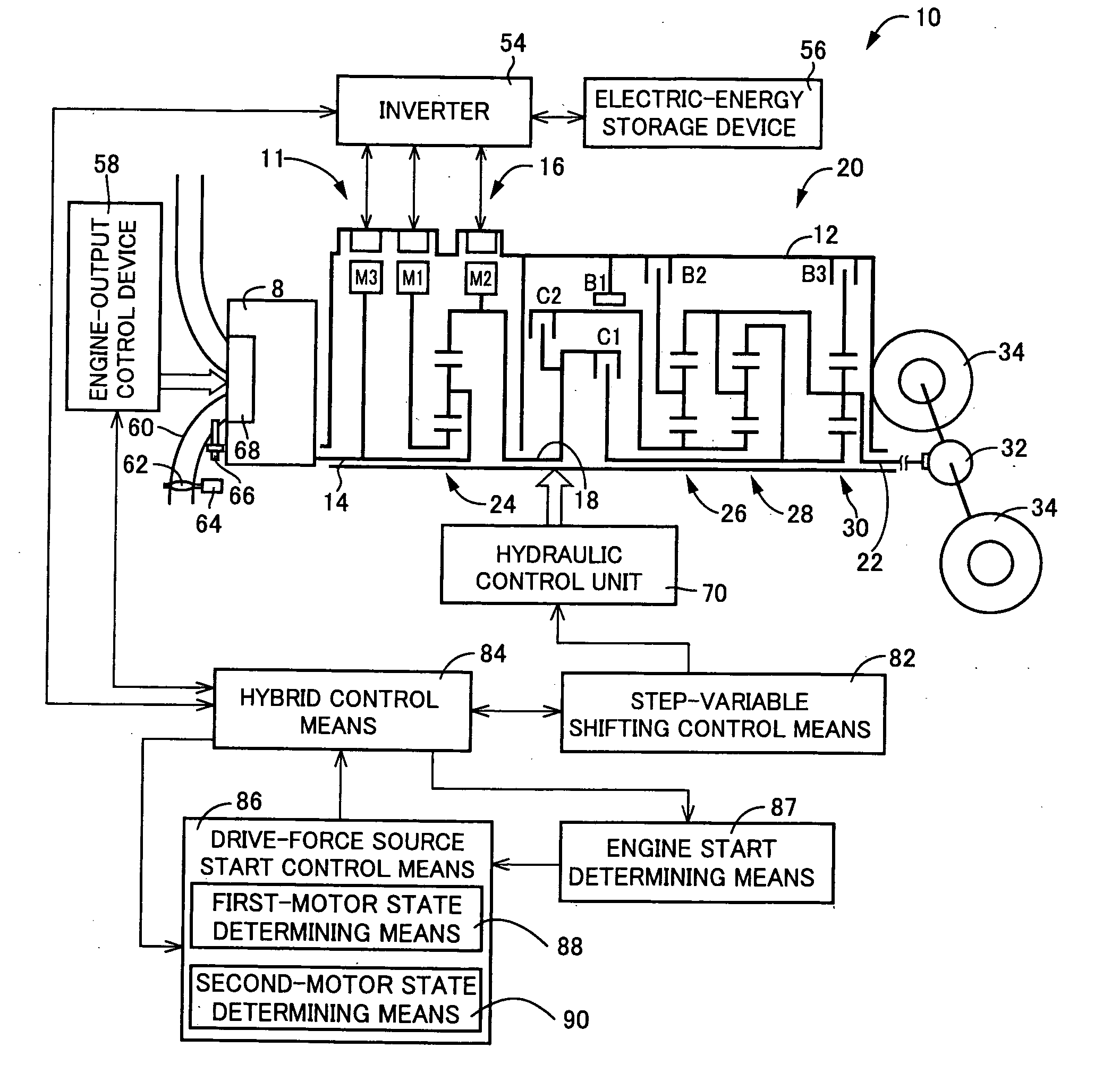
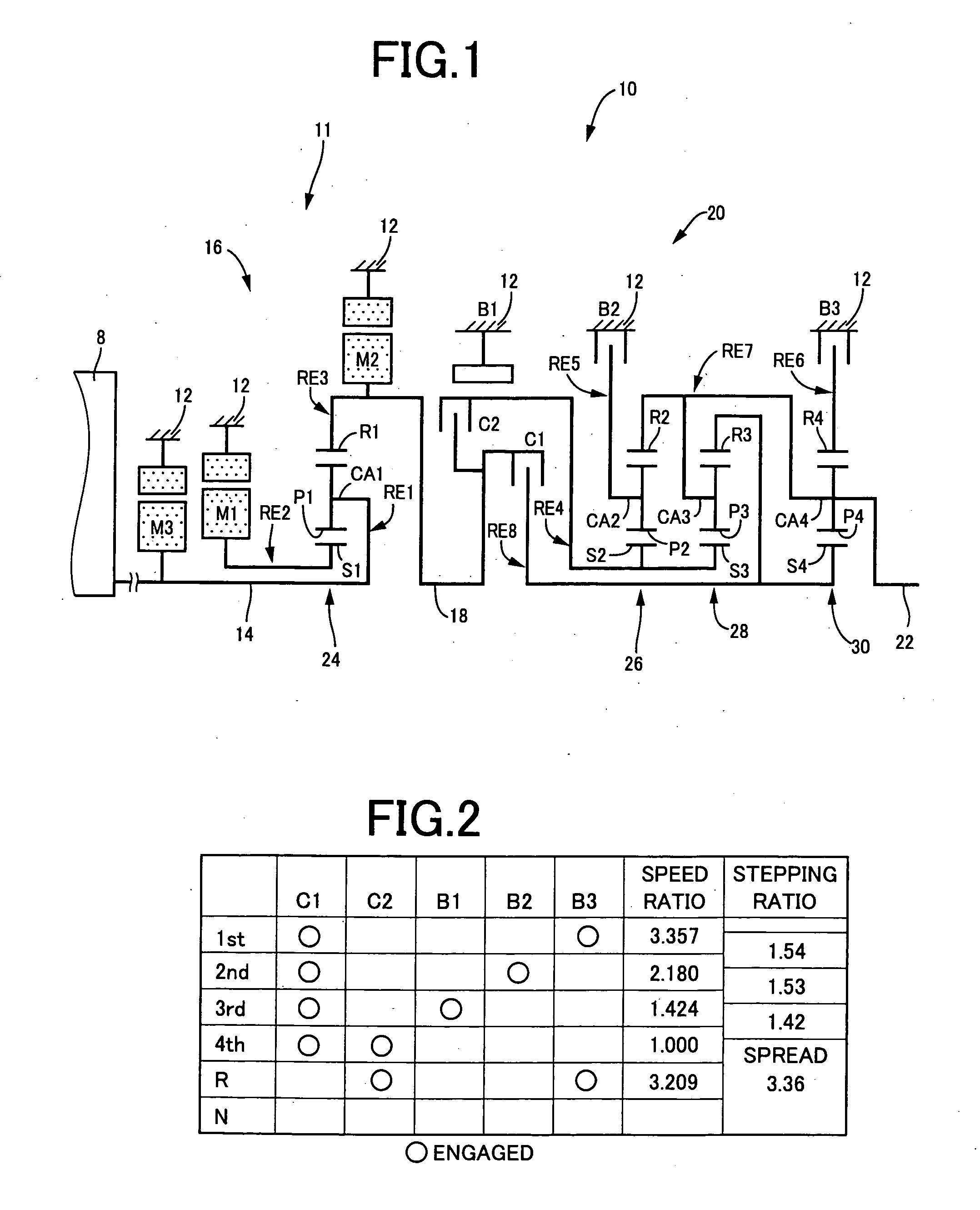
[0140]FIG. 1 is a skeleton diagram for illustrating a transmission mechanism i.e., shifting mechanism 10 constituting a part of a drive apparatus, i.e., drive system for a hybrid vehicle to which the present invention is applied. As shown in FIG. 1, the transmission mechanism 10 includes a transmission case 12 (hereinafter referred to as “a case 12”) mounted on a vehicle body as a non-rotary member, an input shaft 14 disposed inside the case 12 as an input rotary member, a differential portion 11 coaxially connected to the input shaft 14 either directly, or indirectly via a pulsation absorbing damper (vibration damping device), not shown, and serving as a continuously variable transmission portion, an automatic shifting portion, i.e., automatic shifting portion 20 connected in series in a power transmitting path between the differential portion 11 and drive wheels 34 (see FIG. 7) through a power transmitting member 18 (power transmitting shaft), and an output shaft 22 connected to t...

second embodiment

[0230]In the present embodiment, the drive-force source start control means 86 appropriately switches the engine startup modes depending on a gear position (gearshift position), i.e., a gear ratio (gearshift ratio) of the automatic shifting portion 20. In addition, since the present embodiment has the same mechanical structure as that of the first embodiment in a skeletal frame view, description of the same is herein omitted. FIG. 13 is a functional block diagram illustrating a major control function of an electronic control device 80 of the present embodiment according to the present invention.

[0231]Gear-position determining means 92 detects a gear position of the automatic shifting portion 20 for determining whether the relevant gear position belongs to one of a 1st-speed gear position to a 3rd-speed gear position, reverse drive gear position and a 4th-speed gear position. If the relevant gear position is found to belong to the 4th-speed gear position, then drive-force source star...

third embodiment

[0237]With the present embodiment, the drive-force source start control means 86 properly switches the startup modes of the engine 8 to execute the same depending on a shifting condition of the automatic shifting portion 20. In particular, the drive-force source start control means 86 properly switches the startup modes of the engine 8 for executing the same depending on whether the automatic shifting portion 20 is under a shifting operation or whether the engaging elements of the automatic shifting portion 20 remain engaged.

[0238]In the functional block diagram shown in FIG. 13, shifting state determining means 94 makes a query as to whether the automatic shifting portion 20 is under a shifting control or whether the engaging elements of the automatic shifting portion 20 remain disengaged, i.e., whether the power transmitting path between the differential portion 11 and the drive wheels 34 is interrupted. Then, if the automatic shifting portion 20 is under the non-shifting operatio...


PUM


Abstract

In a vehicular power transmitting apparatus provided with an electrically-controlled differential portion in which controlling an operating state of an electric motor controls a differential state of a differential mechanism, a control device for starting up a drive force source in an appropriate mode depending on a vehicle condition can be provided. The control device includes drive-force source start control means 86 for switching start modes of an engine 8 depending on a vehicle condition to achieve an appropriate start mode for the engine 8 depending on the vehicle condition, so that for instance a contracted drive range by a second electric motor can be avoided.

Description

TECHNICAL FIELD[0001]The present invention relates to a control device for a vehicular power transmitting apparatus including an electrically controlled differential portion in which controlling an operating state of an electric motor connected to rotary elements of a differential mechanism controls a differential state between a rotation speed of an input shaft connected to a drive-force source, and a rotation speed of an output shaft. More particularly, it relates to a technology of starting a drive-force source of the vehicular power transmitting apparatus.BACKGROUND ART[0002]There has been known a vehicular power transmitting apparatus including an electrically controlled differential portion in which controlling an operating state of an electric motor connected to rotary elements of a differential mechanism controls a differential state between a rotation speed of an input shaft connected to a drive-force source, and a rotation speed of an output shaft. For instance, a vehicle ...

Claims


Application Information

Patent Timeline
Patent Type & Authority Applications(United States)
IPC IPC(8): B60W10/04B60W20/00B60L50/16B60W10/10
CPCB60K1/02Y10T477/23B60K6/365B60K6/40B60K6/445B60K6/547B60L2240/421B60L2240/423B60L2240/441B60L2240/485B60L2240/486B60W10/06B60W10/08B60W10/115B60W10/30B60W20/00B60W2510/0638B60W2510/081B60W2510/107B60W2510/244B60W2510/246B60W2520/105B60W2520/28B60W2530/10B60W2540/10B60W2540/12B60W2540/16B60W2710/0605B60W2710/0616B60W2710/083F02D29/02F02N11/08F02N2300/2002F16H2037/0873Y02T10/6239Y02T10/6286Y02T10/642B60Y2400/435Y10T477/347Y10T477/33Y10T477/30B60K6/26Y02T10/62Y02T10/64B60K2006/268B60K6/36B60W10/10B60W20/30
Inventor TABATA, ATSUSHIMATSUBARA, TOORUSHIBATA, HIROYUKIKUMAZAKI, KENTAIWASE, YUJIKAIFUKU, MASAKAZU
Owner TOYOTA JIDOSHA KK
Why Eureka
Try Eureka