Flowing water louvered power machine
A louver-type, power engine technology, applied in the direction of reaction engines, hydroelectric power, machines/engines, etc., can solve the problems of reduced cultivated land, intermittent, waste of natural resources, etc., to achieve easy processing and manufacturing, simple structure, and improve rational utilization Effect
Active Publication Date: 2012-06-27
浙江程达科技股份有限公司
View PDF7 Cites 3 Cited by
- Summary
- Abstract
- Description
- Claims
- Application Information
AI Technical Summary
Problems solved by technology
Occasionally there are a few hydroelectric power stations, all of which use the high potential energy of the water drop to generate electricity by building dams and storing water, which causes intermittent shipping, flooding a large number of fields and reducing cultivated land, which greatly wastes the existing natural resources
Method used
View moreImage
Smart ImageViewing Examples

Examples
Embodiment Construction
Login to View More PUM
 Abstract
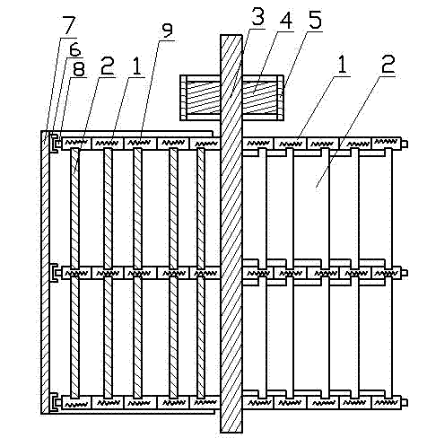
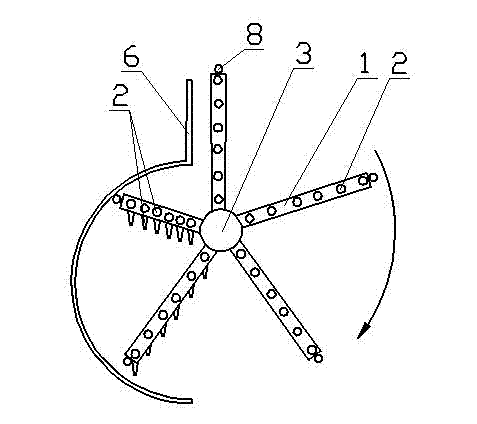
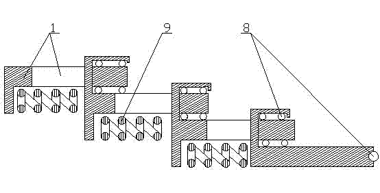
The invention discloses a flowing water louvered power machine. A roller (8) is arranged on the slide fitting part of two slide expansion joints (1) on a slideable telescopic bracket, a spring (9) is arranged on the slide expansion joints (1); a louvered free rotation water blocking plate (2) is arranged on the slideable telescopic bracket, one end of the slideable telescopic bracket is arranged on a power shaft (3), and the other end of the slideable telescopic bracket is provided with the roller; the slideable telescopic bracket contacts with a bracket-contracted supporting guide rail (6) by the roller (8); the bracket-contracted supporting guide rail (6) is arranged on a water guide blocking sheet (7) to form an integral structure; a bearing (4) is arranged on the power shaft (3); and the power shaft (3) is directly or indirectly connected with a shaft of the equipment requiring power by the bearing (4) and a bearing base (5). The flowing water louvered power machine with simple structure and convenience in manufacturing is adopted to achieve flowing water power resource, so that the current natural resources are greatly used and protected, the rational utilization rate of resources is improved; the flowing water louvered power machine is a green, environment-friendly and efficient water energy power machine which uses natural environment resources.
Description
Technical field [0001] The invention relates to a flowing water louver type power machine that utilizes the energy of the water in the diversion canal and drainage canal of a hydroelectric power station that stores water to generate electricity, and the water flowing in the water area in nature. Background technique [0002] There are many rivers and streams on the earth, and there are very few that use the energy of flowing water for power or power generation. Occasionally, there are a few hydroelectric power stations that use the high potential energy of the water drop to generate electricity by building dams and storing water. This has caused intermittent shipping, a large number of flooded fields and reduced cultivated land, which greatly wasted the existing Natural resources. Summary of the invention [0003] The purpose of the present invention is to provide a kind of power equipment that uses the energy of flowing water as power in the diversion canal and drainage canal of...
Claims
Login to View More Application Information
Patent Timeline
 Patent Type & Authority Applications(China)
IPC IPC(8): F03B3/00F03B3/12F03B3/18
CPCY02E10/223Y02E10/20Y02P70/50
Inventor 徐浩钟徐園植余虹仪
Owner 浙江程达科技股份有限公司