Charging system for cupola furnaces

A technology of feeding system and cupola, which is applied to furnaces, vertical furnaces, furnace components, etc., can solve the problems of large footprint, large width, and low utilization rate of the feeding machine, and achieves simple and reliable structure. Effect

Active Publication Date: 2012-06-27
姚立猛 +1
View PDF8 Cites 8 Cited by
  • Summary
  • Abstract
  • Description
  • Claims
  • Application Information

AI Technical Summary

Problems solved by technology

The process of feeding the cupola in the above-mentioned prior art has obvious disadvantages: firstly, the feed barrel of this kind of feeder enters into the cupola through the feed port on the side, and because the height and diameter of the feed barrel are usually large, Coupled with the height of the frame-shaped beam frame of the traveling mechanism of the monorail feeder, the steel rope and the hook, not only the height and width of the feeding port on the side of the cupola are larger (for example, the melting rate is 10 per hour. The feeding port of the cupola up to 12 tons is about 4 to 5 meters high and 1.6 to 1.8 meters wide, and the feeding port of the cupola with a melting rate of 3 tons is 2.5-2.6 meters high, and the width is basically the same as the inner diameter of the furnace) , resulting in more external air being sucked into the inner cavity of the furnace body from the upper space of the charging port during operation of the cupola, and the suction generated by the hot air flow and the fan of the dust removal device is consumed by the entry of the external air at the upper part of the charging port Lose
The two main charging machines mentioned above (monorail charging machine and guide rail charging machine) belong to a single system, that is, each cupola must be equipped with a corresponding charging machine, so the utilization rate of the charging machine is low (half the time in idle state)
Secondly, the feeder occupies a large area, so the precious land resources are greatly wasted, coupled with the high land price, the investment of the enterprise is also greatly increased.

Method used


Image

  • Charging system for cupola furnaces
  • Charging system for cupola furnaces
  • Charging system for cupola furnaces

Examples


Embodiment 1

[0055] (Embodiment 1, the charging system of the cupola)

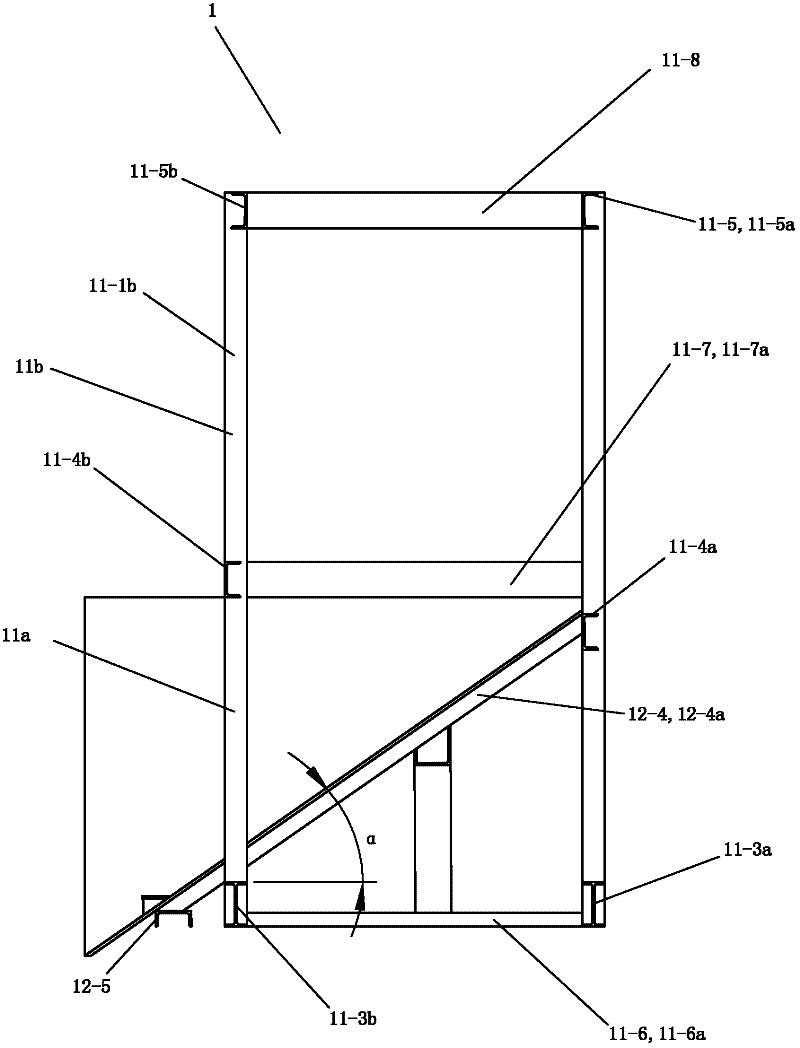
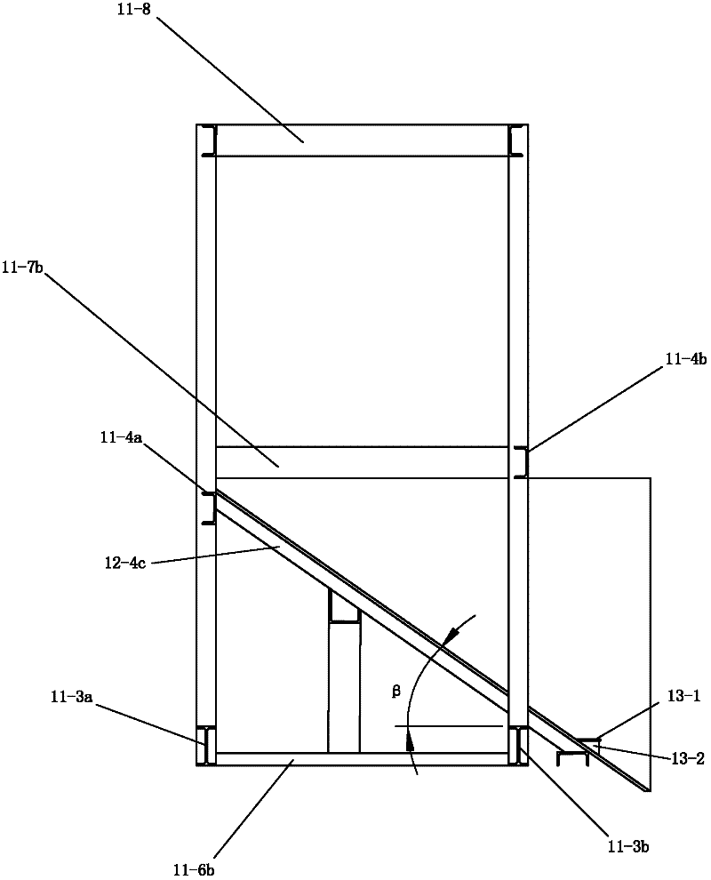
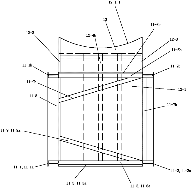
[0056] See figure 1 and Figure 6 , The feeding system of the cupola of the present invention includes a material guide device 1 and a feeding device 3 .

[0057] There are two material guides 1, the structures of the two material guides 1 are symmetrical, and the two material guides (1) are basically symmetrical with respect to a front-to-back vertical plane between them. The front side of the cupola. The two material guides 1 are divided into left side material guide 1a and right side material guide 1b according to their left and right positions.

[0058] Both material guiding devices 1 include a supporting structure, a material guiding structure 12 and a buffer device 13 . The support structure is a wedge-shaped support base or steel structure support frame made of cement and bricks (this embodiment is a support frame composed of straight steel components fixedly connected to each other in sequence, and the stra...


PUM


Abstract

The invention discloses a charging system for cupola furnaces. The charging system comprises a feeding device and two material guide devices, wherein the two material guide devices are respectively arranged at the front side of the corresponding cupola furnace and are divided into a left side material guide device and a right side material guide device according to different left and right positions of the two material guide devices, and the two material guide devices respectively comprise support structure elements and material guide structure elements and are basically symmetrical relative to a radial vertical surface positioned between the two material guide devices. Each material structure element comprises a material guide groove, an opening of the material guide groove faces the upper back part, the front end part of the material guide groove is fixedly connected onto a support frame, and in addition, the material guide groove is arranged in an inclined mode that the front part is higher and the back part is lower. Guide rails of the feeding device are horizontally arranged above the front and back middle parts of the two material guide devices in the left and right directions, so a hopper can discharge materials above any one of the two material guide devices, and the use of two cupola furnaces can be met.

Description

technical field [0001] The invention relates to the field of cupola manufacture, in particular to a system for feeding materials into the cupola. Background technique [0002] Cast iron melting is one of the important links to obtain high-quality castings. Cast iron melting equipment includes mixing furnace, three-section furnace, electric furnace (electric arc furnace or induction furnace), cupola and so on. Among them, the cupola furnace is the most widely used, and the total output of cast iron parts exceeds 90%. This is because the cupola melting is characterized by simple equipment, convenient operation, high production efficiency, continuous production, and low cost. Although the temperature and composition control of the cupola furnace is not as easy as that of the electric furnace, it can basically meet the production requirements of general iron castings. Therefore, the cupola furnace is still the main equipment for casting iron melting. The cupola is a cylindrica...

Claims


Application Information

Patent Timeline
Patent Type & Authority Applications(China)
IPC IPC(8): F27B1/20F27D3/10
Inventor 姚立猛陈姚
Owner 姚立猛
Why Eureka
Try Eureka