
Bridge dynamic deflection facula imaging measuring device and method

An imaging measurement and light spot technology, which is applied to measurement devices, optical devices, instruments, etc., can solve the problems of reducing the resolution and range, the effect and accuracy are not as good as conventional lenses and one-time imaging, affecting the actual measurement effect, etc., and achieves a degree of automation. high effect

Inactive Publication Date: 2012-06-27
CHINA RAILWAY BRIDGE SCI RES INST LTD +1
View PDF6 Cites 32 Cited by
  • Summary
  • Abstract
  • Description
  • Claims
  • Application Information

AI Technical Summary

Problems solved by technology

There are a few methods in the prior art that can measure the dynamic deflection of bridges. The method most similar to the present invention is to use a white LED light as a light source, and use a CCD to collect images behind the telescope eyepiece of the theodolite to measure the dynamic deflection, but this method has the following defects : 1. The white light source is easily interfered by strong sunlight during the day, and interfered by external light sources such as car lights, street lights, and construction site searchlights at night, resulting in large errors in measurement and affecting the actual measurement effect; 2. The optical path is after passing through the telescope. After passing through the atmosphere and then through the conventional lens and CCD imaging, that is to say, it has passed through the imaging system twice, which reduces the resolution and range, and the measurement effect and accuracy are not as good as the conventional lens and one-time imaging.

Method used


Image

  • Bridge dynamic deflection facula imaging measuring device and method
  • Bridge dynamic deflection facula imaging measuring device and method
  • Bridge dynamic deflection facula imaging measuring device and method

Examples


Embodiment Construction

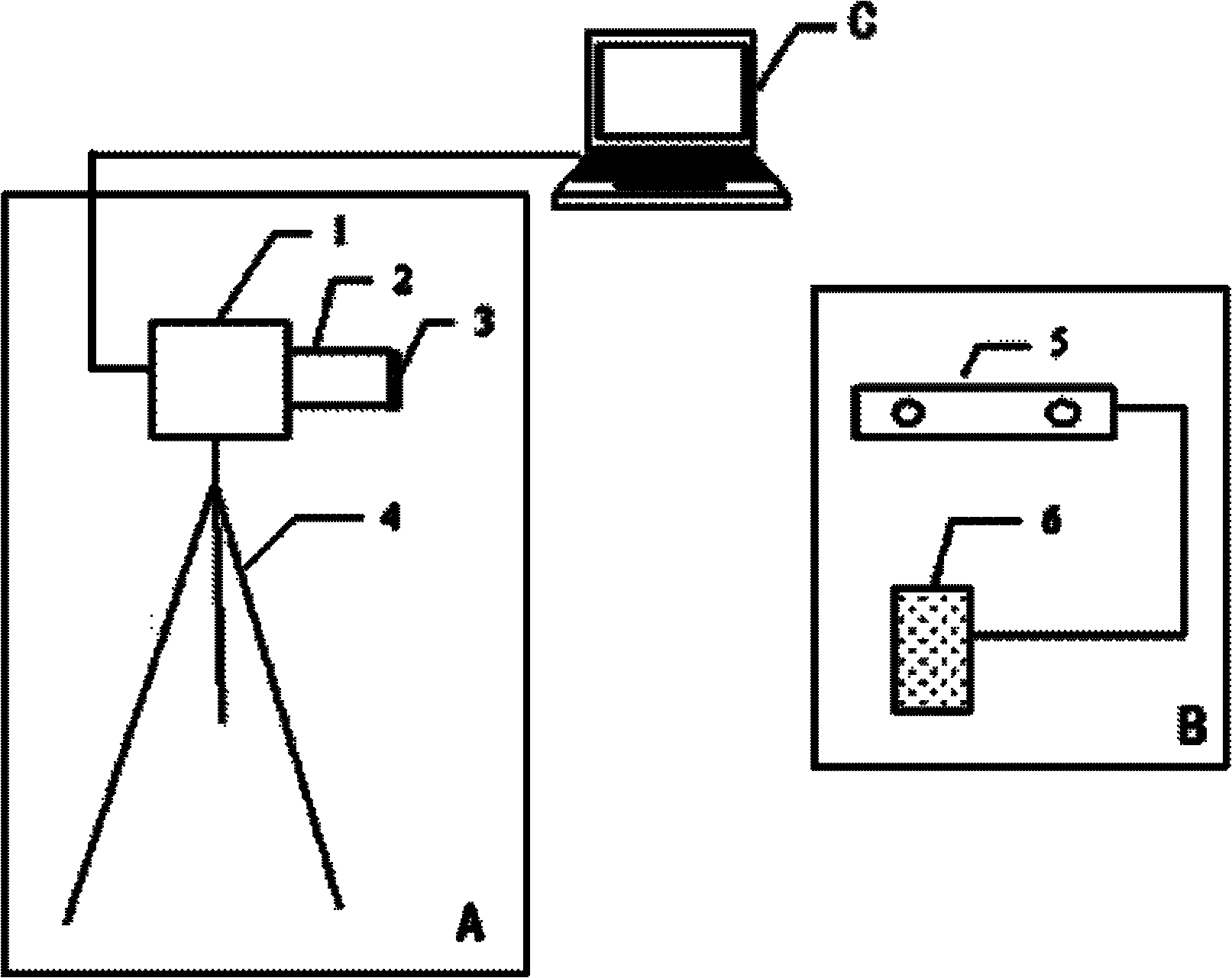
[0022] The present invention will be further described below in conjunction with the accompanying drawings and embodiments. figure 1 It is a connection schematic diagram of the bridge dynamic deflection spot imaging measurement device of the present invention. It is mainly composed of image acquisition device A, measuring point marker B, and computer C. Image acquisition device A is mainly composed of CCD1, lens 2, optical filter 3, and tripod 4. Optical filter 3 is fixed on the front end of lens 2. , the lens 2 is fixed at the fixed interface of CCD1, the computer C is connected to CCD1 through the data line, provides power to CCD1 and processes the image data transmitted by CCD1; the measuring point marker B is mainly composed of blue LED light 5 and lithium battery 6, the lithium battery 6 provides power for the blue LED light 5.

[0023] In this embodiment, the pixel of the CCD1 of the image acquisition device A is 1280×1024, and the lens 2 is a 12.5mm-75mm zoom lens; Li...


PUM


Abstract

Provided is a bridge dynamic deflection facula imaging measuring device and a method. A blue light-emitting diode (LED) lamp is arranged at the position of a deflection measure point of a structure to be measured, light is processed by a charge coupled device (CCD) in a photoelectrical coupling mode after passing through a filtering and central-long focus lens, optical signals of the deflection measure point of the structure to be measured are converted into picture signals to be transmitted to a computer which works out a location value of a facula corresponding to the LED lamp on a receiving screen, then the position value of the deflection measure point of the structure to be measured is calculated, and bridge dynamic deflection measurement in a bridge measurement and health monitoring process is achieved.

Description

technical field [0001] The invention relates to a bridge dynamic deflection spot imaging measurement device and method, belonging to the technical field of bridge detection and monitoring. Background technique [0002] In the process of bridge inspection and health monitoring, the deflection of the bridge is an important parameter that is very concerned about the three key issues of strength, stiffness, and stability of the bridge structure. The force characteristics have important theoretical value, therefore, the precision and accuracy of deflection measurement is very important. Under this demand, researchers at home and abroad have developed many new deflection measurement methods, among which the representative ones are: dial indicator method, connected pipe method, level method, GPS deflection measurement method, and laser method. They all have some problems and deficiencies to varying degrees, and are basically suitable for static deflection measurement. Therefore, c...

Claims


Application Information

Patent Timeline
IPC IPC(8): G01B11/16
Inventor 王翔王波许兆斌刘源周启茂柴小鹏程洪全余昆曾宪双陈晓琳
Owner CHINA RAILWAY BRIDGE SCI RES INST LTD
Learn More