Device for detecting blade strain on line based on optical fiber grating

A fiber grating and detection device technology, which is applied to measurement devices, optical devices, instruments, etc., can solve the problems of difficulty in online monitoring, poor stability, and vulnerability to lightning strikes, and achieve quasi-distributed measurement and high long-term stability. Effect

Inactive Publication Date: 2012-06-27
YANTAI RAYTRON TECH
View PDF7 Cites 8 Cited by
  • Summary
  • Abstract
  • Description
  • Claims
  • Application Information

AI Technical Summary

Problems solved by technology

However, due to various conditions at present, traditional electronic strain gauges have poor long-term stability, and are easily struck by lightning when they are in operation, making it difficult to achieve online monitoring.

Method used


Image

  • Device for detecting blade strain on line based on optical fiber grating
  • Device for detecting blade strain on line based on optical fiber grating
  • Device for detecting blade strain on line based on optical fiber grating

Examples


Embodiment 1

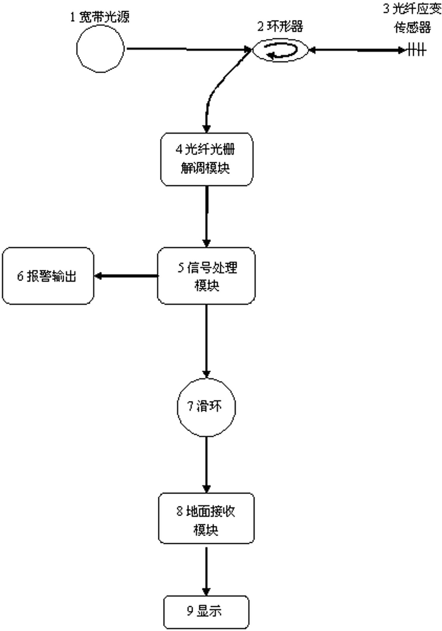
[0028] Such as figure 1 As shown, a fiber grating-based on-line fan strain detection device includes a broadband light source 1, a circulator 2, a fiber grating strain sensor 3, a fiber grating demodulation module 4 that converts optical signals into electrical signals, and converts electrical signals into The signal processing module 5 of the strain information, the slip ring 7, the ground receiving module 8, the output end of the broadband light source 1 is connected with the input end of the circulator 2 through an optical fiber, and the output end of the circulator 2 is connected with the fiber grating strain sensor 3 The input end of the circulator 2 is connected through an optical fiber, and the return end of the circulator 2 is connected with the input end of the fiber grating demodulation module 4 through an optical fiber;

[0029] The output end of the fiber grating demodulation module 4 is connected to the input end of the signal processing module 5 through a wire, a...

Embodiment 2

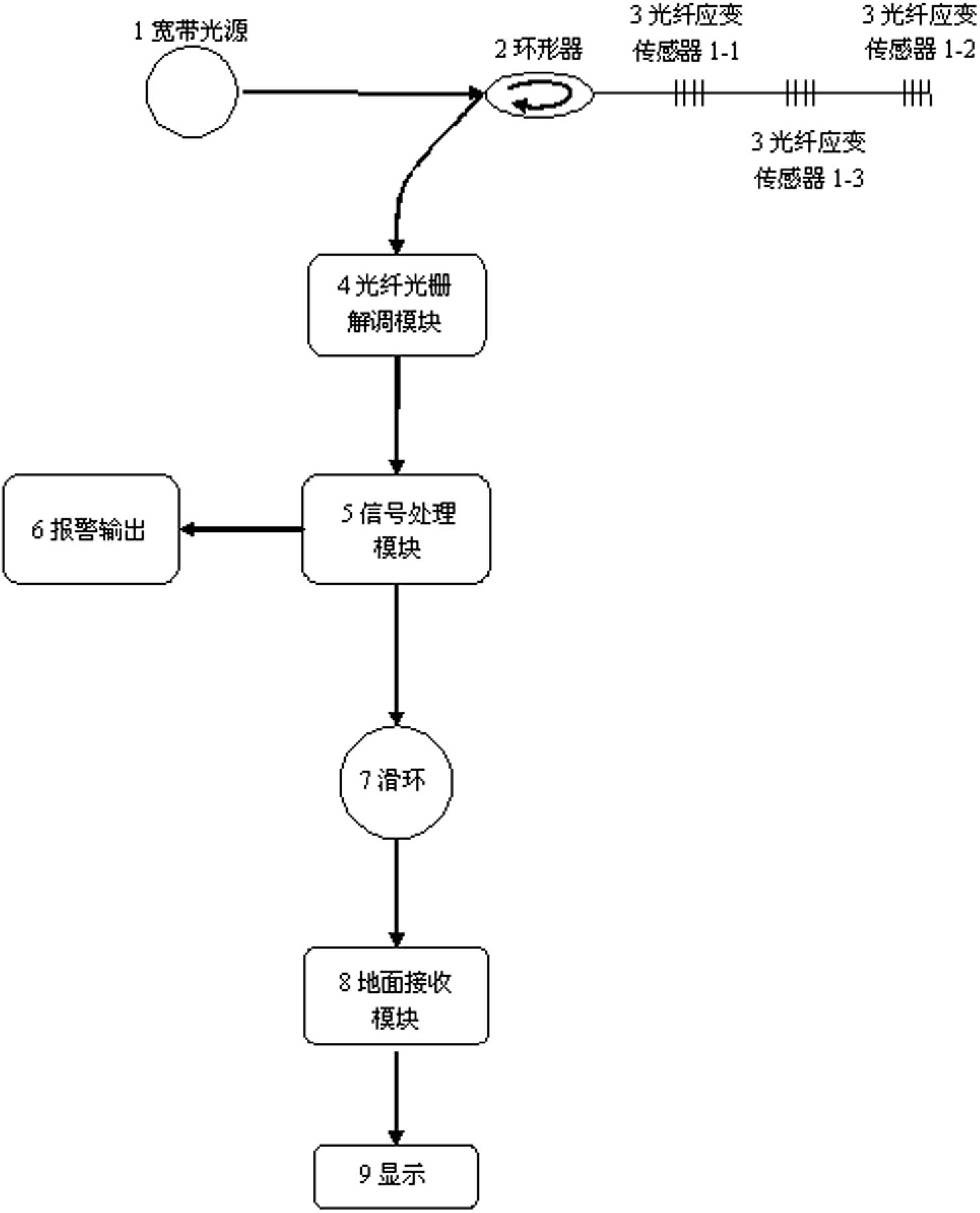
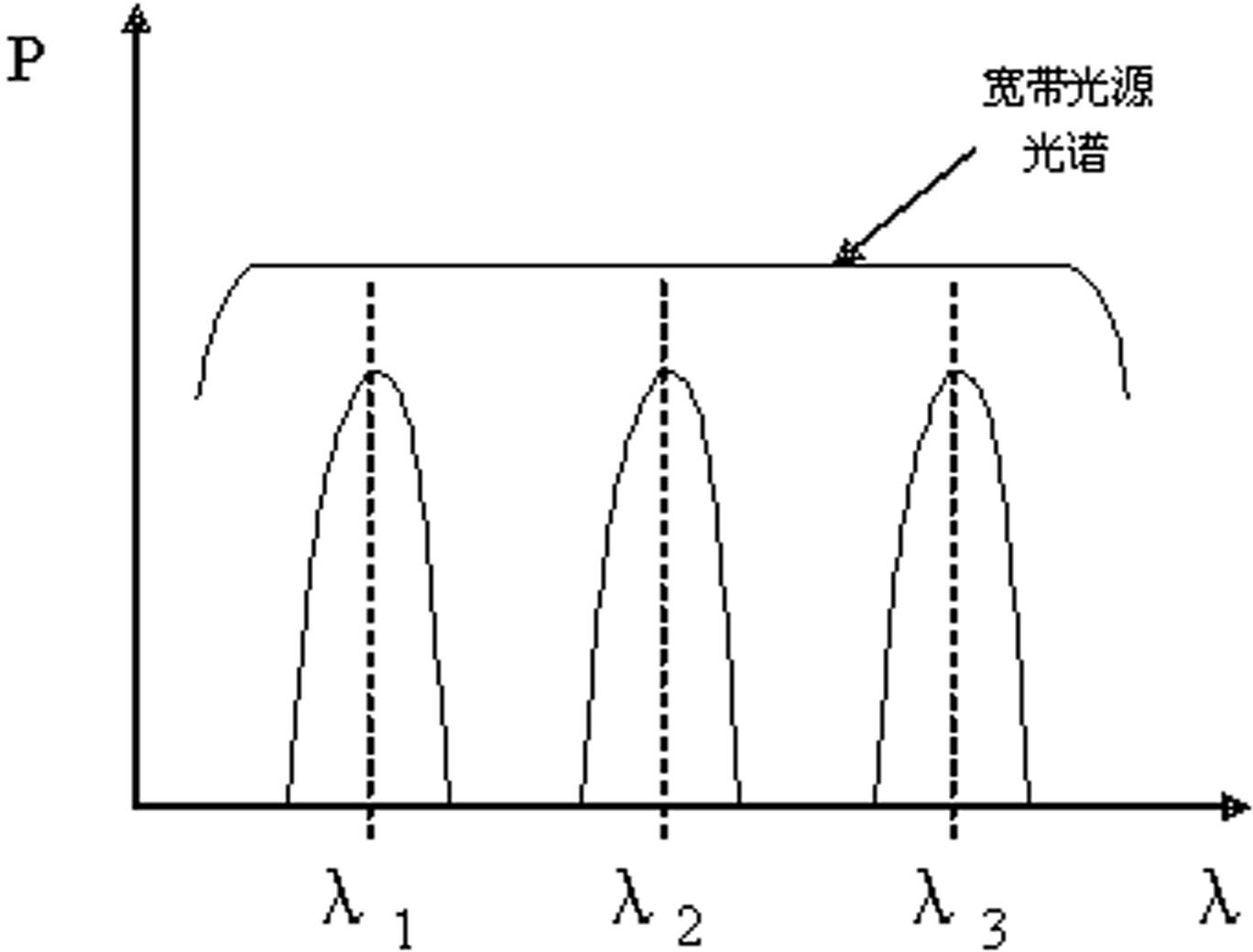
[0037] Such as figure 2 As shown, the difference between embodiment 2 and embodiment 1 is that it includes 3 fiber grating strain sensors 3. The number of fiber grating strain sensors 3 is equal to the quotient of dividing the spectral width of the broadband light source 1 by the spectral width of a single sensor. When the result is a decimal, keep the integer part and discard the decimal part. Three grating fiber optic strain sensors 3 are connected in series from end to end, using wavelength division multiplexing technology, such as image 3 As shown, measure multiple detection points of the blade to realize the quasi-distributed measurement of the blade strain; or through a splitter connection, the input end of the splitter is connected to the output end of the circulator 2, and each FBG strain The input ends of the sensors 3 are all connected to an output end of the splitter, and the broadband light emitted by the broadband light source 1 is transmitted to the FBG strain...


PUM


Abstract

The invention relates to a device for detecting fan strain on line based on an optical fiber grating, and belongs to the field of fan blade detection in the wind power generation industry. The device comprises a broad band light source, a circulator, an optical fiber grating strain sensor, an optical fiber grating demodulation module, a data processing module, a warner, a sliding ring, a ground receiving module and a displayer. According to the device, the strain quantity of a blade can be acquired by demodulating and calculating the variation quantity of a central wavelength of the optical fiber grating according to the linear relation between the variation of the central wavelength of the optical fiber grating and the variation of the blade strain, so that real-time and on-line detection can be realized. The device can be used for detecting the strain of a plurality of points of the fan blade in real time on line by using a wavelength division multiplexing technology and has the characteristics of small volume, capacity of marking wavelengths, on-line detection, long-term stability and the like, and is not interfered with electromagnetism.

Description

technical field [0001] The invention relates to the field of detection of fan blades in the wind power generation industry, in particular to an online strain detection device based on a fiber Bragg grating (FBG) strain sensor under the running state of the fan blades. Background technique [0002] With the continuous development of society, the demand for energy continues to increase, especially the demand for electricity, which has become an indispensable resource for all walks of life. As an important clean and renewable energy, wind energy has been greatly developed all over the world. By the first half of 2011, the total number of installed wind turbines in my country had reached the first place in the world. [0003] Blades are the main components of wind turbines, and their condition monitoring is very important. The condition of the blades is directly related to whether the fan can operate normally, and the blades will be deformed to varying degrees in the wind state....

Claims


Application Information

Patent Timeline
Patent Type & Authority Applications(China)
IPC IPC(8): G01B11/16
Inventor 霍佃恒马宏张永庆张勇靳占军董彦冬
Owner YANTAI RAYTRON TECH
Why Eureka
Try Eureka