

Circuit board testing system
A test system and circuit board technology, which is applied in the direction of electronic circuit test, etc., can solve the problems of limiting the number of test nodes and slow detection speed, etc., and achieve the effect of improving self-inspection and detection, good scalability, and strong anti-interference ability
- Summary
- Abstract
- Description
- Claims
- Application Information
AI Technical Summary
Problems solved by technology
Method used
Image

Examples
Embodiment 1
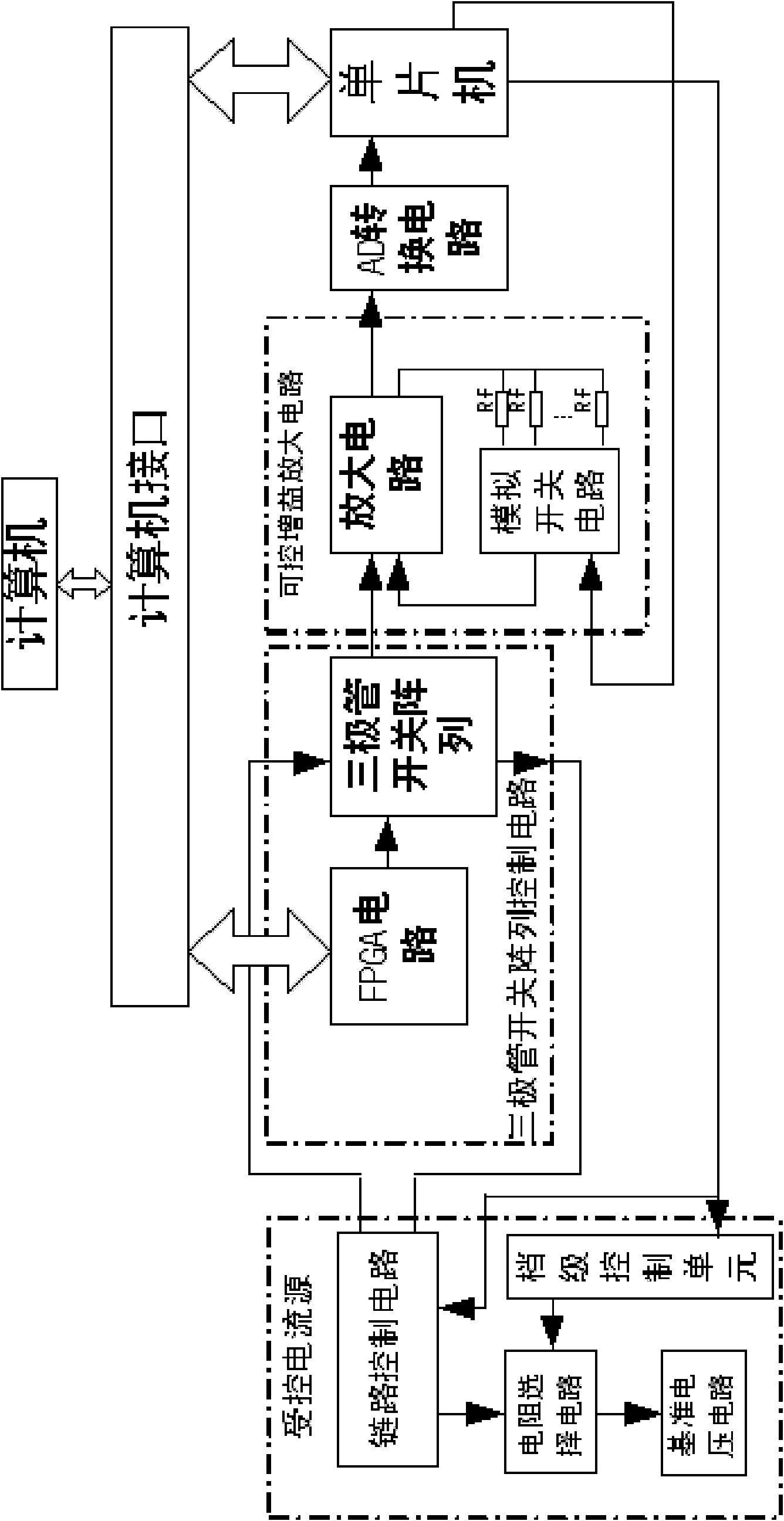
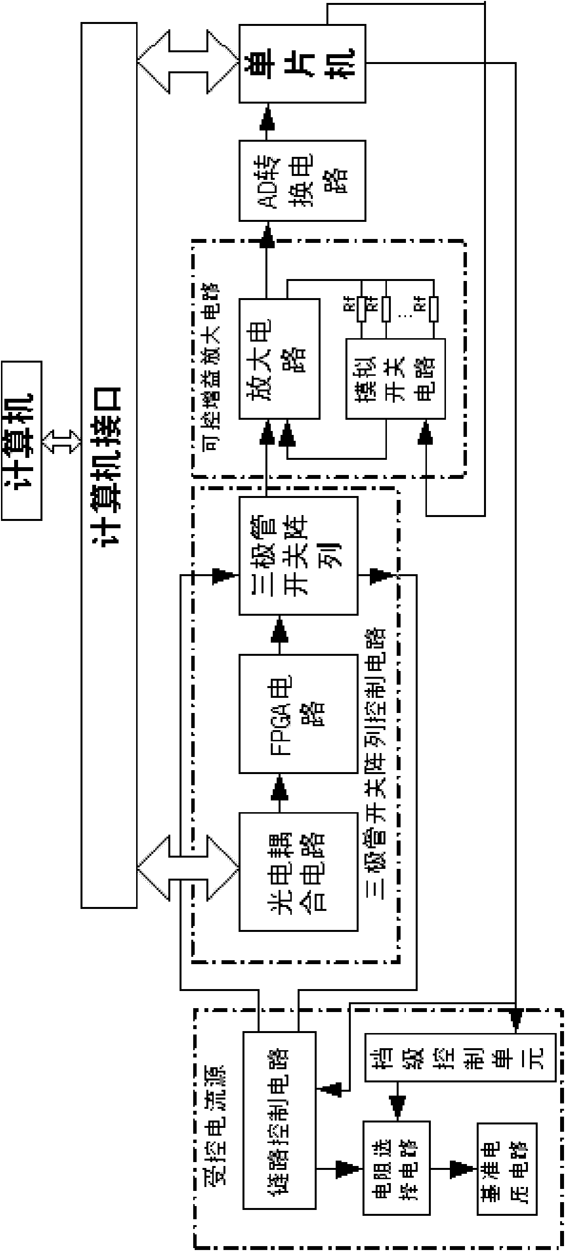
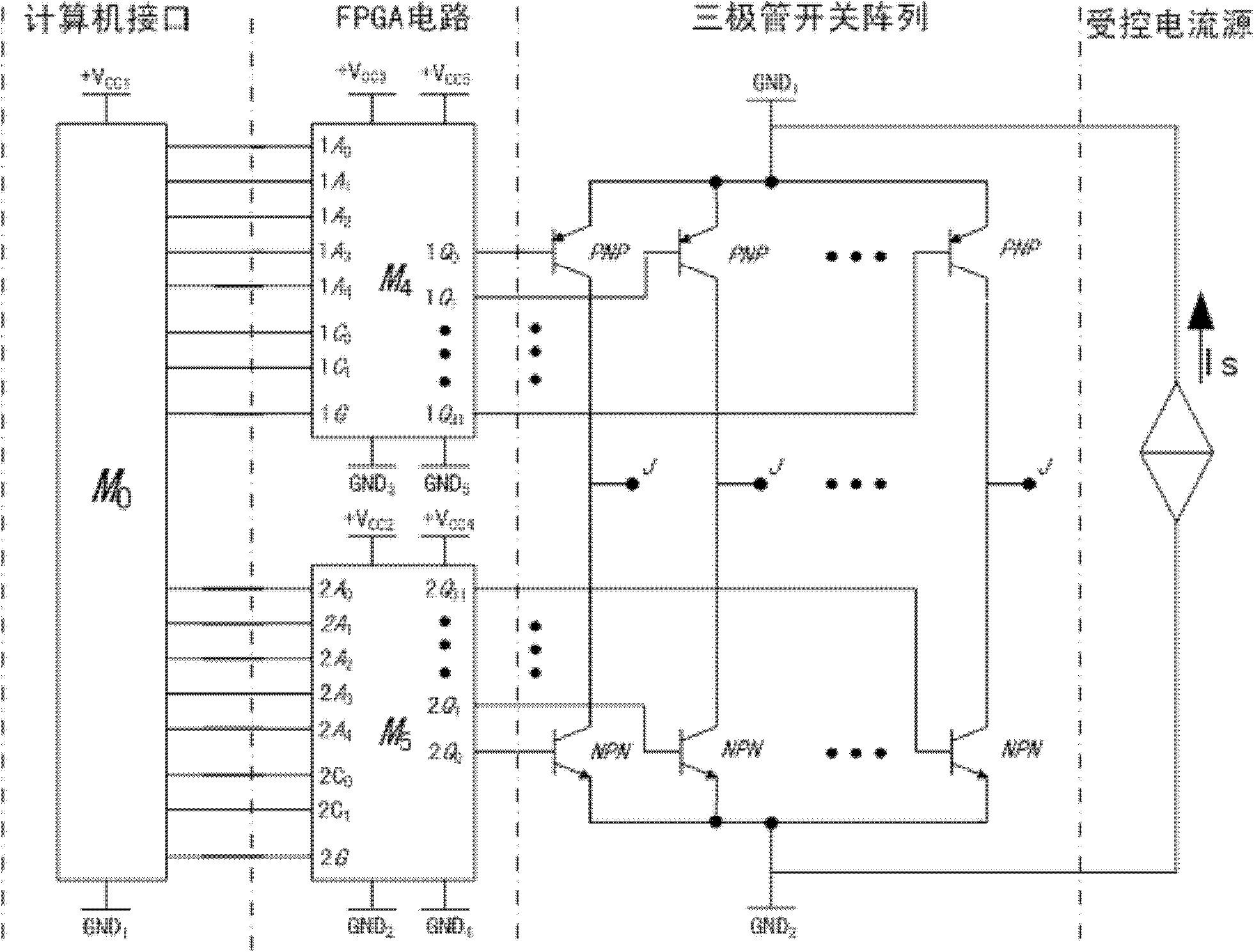
[0034] like figure 1 , a contact circuit board testing system, comprising: a computer interface M0, the FPGA circuit in the triode switch array control circuit is connected to the computer interface M0; the output end of the FPGA circuit is connected to the triode switch array; The triode switch array includes at least two groups of paired transistor circuits, the paired transistor circuit includes a PNP type and an NPN type transistor, the collectors of the PNP type and NPN type transistors are connected, and each PNP type transistor in the triode array circuit The emitters of the transistors are connected to form the first common point GND1, and the emitters of the NPN transistors in the transistor array circuit are connected to form the second common point GND2. The terminal connected to the electrodes is the test node J; the two common points of the triode switch array are respectively connected to a controlled current source, and the current generated by the controlled cu...
Embodiment 2
[0121] Self-test function, used to detect the working condition of the triode switch circuit. Control the base of the triode so that any group of triodes is turned on, and the voltage between the two points AB is:
[0122] u AB =U ecs + U ces = 2U ces (12)
[0123] Among them: U ecs , U ces is the saturated conduction voltage drop of the triode, U ecs =U ces , let U ecs + U ces = 2U ces . Obviously, by detecting the detection voltage U between two points AB AB , you can judge the working condition of the triode.
[0124] To test the functional principle, the base of the triode is controlled by the FPGA, so that the triode is cross-conducted to ensure that the PNP and NPN transistors in each pair of tubes are not turned on at the same time, and the voltage between the two points AB is:
[0125] u AB =(U ecs + U ces )+I x R x = 2U ces +I x R x (13)
[0126] Get R from formula (2) x :
[0127] R x = ...
Embodiment 3
[0136] On the basis of embodiment 1, the detection working method of the contact circuit board testing system of the present embodiment comprises the following steps:
[0137] ① Place the standard circuit board horizontally on the test platform of the contact circuit board test system, so that all the probes connected to the test node J of the triode switch array are in contact with the standard circuit board;
[0138] 2. Control the second FPGA circuit M5 by computer to cut off the NPN transistors in any pair of transistor circuits in the transistor array, and make the rest of the NPN transistors in the transistor switch array fully conduct; and the computer controls the first FPGA The circuit M4 makes the PNP-type transistors in the pair of tube circuits conduct, and the remaining PNP-type transistors in the transistor switch array are all cut off, and the test node J in the pair of tube circuits is set as a test reference point;
[0139] ③ If there is no detection voltage ...
PUM
 Abstract
Description
Claims
Application Information