Method for calculating quenching medium heat exchange coefficient by combining finite element method with inverse heat conduction method

A quenching medium and heat transfer coefficient technology, which is applied in the fields of calculation, electrical digital data processing, special data processing applications, etc., can solve the problems of inability to accurately control the quenching cooling rate of industrial parts, the error of heat transfer coefficient, and the difficulty in measuring the cooling rate.

Active Publication Date: 2012-06-27
HARBIN INST OF TECH
View PDF2 Cites 15 Cited by
  • Summary
  • Abstract
  • Description
  • Claims
  • Application Information

AI Technical Summary

Problems solved by technology

[0003] The purpose of the present invention is to solve the problem that the method of obtaining the heat transfer coefficient through the inverse heat transfer calculation method has errors, which leads to the inability to accurately control the quenching cooling rate of industrial parts, and the problem that the cooling rate is difficult to measure, and then provides a combination of finite element method and inverse The Method of Calculating the Heat Transfer Coefficient of Quenching Medium by Heat Transfer Method

Method used


Image

  • Method for calculating quenching medium heat exchange coefficient by combining finite element method with inverse heat conduction method
  • Method for calculating quenching medium heat exchange coefficient by combining finite element method with inverse heat conduction method
  • Method for calculating quenching medium heat exchange coefficient by combining finite element method with inverse heat conduction method

Examples


specific Embodiment approach 1

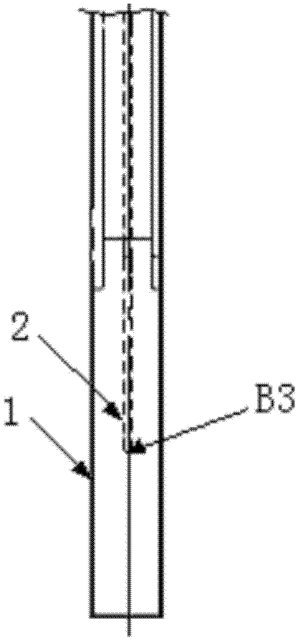
[0041] Specific implementation mode one: combine Figure 1 to Figure 7 Describe this embodiment, the method for calculating the heat transfer coefficient of the quenching medium in combination with the finite element method and the reverse heat transfer method of this embodiment, the specific process of the method for calculating the heat transfer coefficient of the quenching medium is:

[0042] Step 1. Heat the probe body 1 with the thermocouple 2 inserted inside it in the heating furnace to 860°C and keep it evenly, and then quickly quench it into the quenching medium with a transfer time of no more than 2s. The temperature of the quenching medium is set to T w , using a computer system to record the temperature of the internal feature point B3 of the probe body 1 measured by the thermocouple 2, and draw a cooling curve, that is, to obtain the cooling curve of the quenching medium at this temperature;

[0043] Step 2. Based on the ABAQUS finite element platform, use the fini...

specific Embodiment approach 2

[0070] Embodiment 2: The quenching medium in the step 1 of this embodiment is water, No. 20 engine oil or UCON-A (water-soluble polymer) quenching agent.

specific Embodiment approach 3

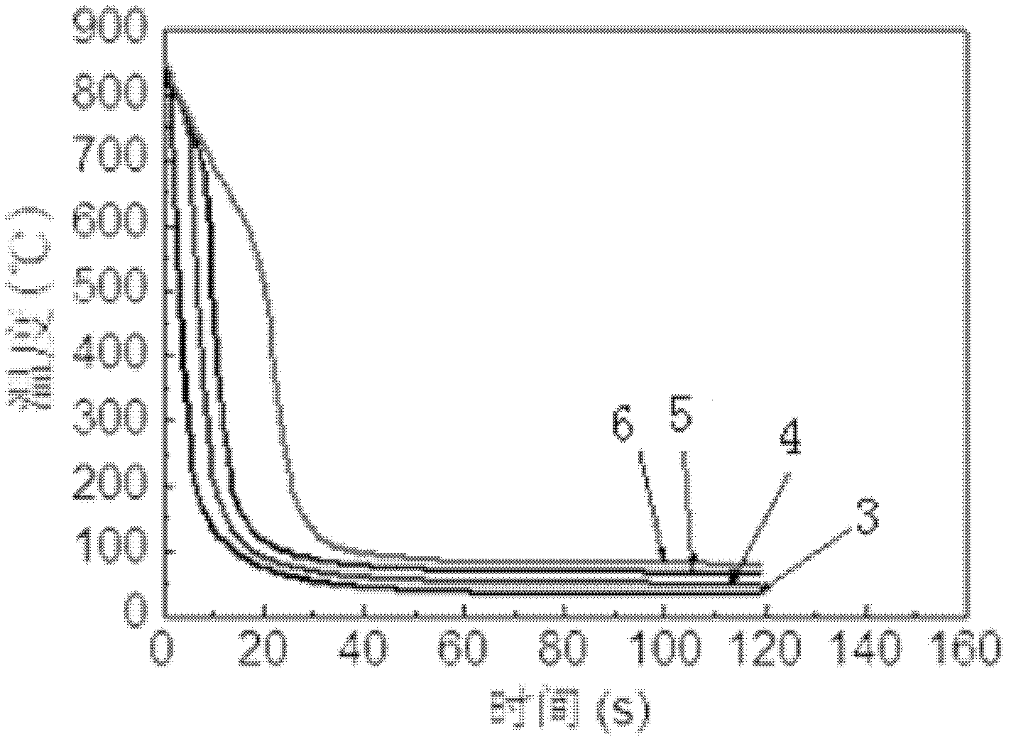
[0071] Embodiment 3: When the quenching medium in step 1 of this embodiment is water, the temperature of the quenching medium is set to 25°C, 45°C, 60°C or 80°C. Determine the temperature of the quenching medium according to the physical properties of the quenching medium and the actual operating temperature. For the cooling curve, see figure 2 .


PUM

PropertyMeasurementUnit
diameteraaaaaaaaaa

Abstract

The invention discloses a method for calculating a quenching medium heat exchange coefficient by combining a finite element method with an inverse heat conduction method, which relates to a method for calculating a quenching medium heat exchange coefficient. The method comprises the following steps of: using a probe body, testing by an experiment to obtain the cooling curve of an internal point of the body, establishing a finite element model of the probe body, simulating a temperature field, and verifying the one-dimensional property of a problem; establishing a one-dimensional heat conduction micro equation and a sensitive coefficient equation under a coordinate system, and solving the heat-flow density value of the surface of the body surface by using the inverse heat conduction method; and verifying the measured temperature of the internal point of the probe in comparison to a calculated value, namely the heat exchange coefficient of the quenching medium calculated according to the Newton heat exchange law, so that the solution accuracy is ensured. The method is used for calculating the heat exchange coefficient of quenching medium.

Description

technical field [0001] The invention relates to a method for calculating the heat transfer coefficient of a quenching medium, which belongs to the field of technical parameter design of metal thermal processing. Background technique [0002] Quenching treatment is a very important heat treatment method for parts in actual production to obtain the required mechanical properties, and the quenching medium is undoubtedly the most important influencing factor. The essential role of the quenching medium is reflected between it and the metal surface. The size of the heat transfer coefficient. Seeking an accurate method to obtain the size of the heat transfer coefficient has important engineering practical significance. At present, the main method to study this problem is the inverse heat transfer calculation method. This method is a theoretical mathematical discrete calculation method with certain inevitable errors, which makes it impossible to accurately control the quenching coo...

Claims


Application Information

Patent Timeline
Patent Type & Authority Applications(China)
IPC IPC(8): G06F17/50
Inventor 朱景川杨夏炜来忠红何东刘勇
Owner HARBIN INST OF TECH
Why Eureka
Try Eureka