Semi-automatic end scalding equipment

A semi-automatic and equipment technology, applied in the direction of electrical components, circuits, connections, etc., can solve the problems of perm smoke harmful to human body, prone to operation errors, and influence on processing accuracy, so as to achieve quality improvement, consistent processing size, and high degree of automation Effect

Active Publication Date: 2012-06-27
TIANJIN HUAZHIYANG SPECIAL CABLE
View PDF4 Cites 3 Cited by
  • Summary
  • Abstract
  • Description
  • Claims
  • Application Information

AI Technical Summary

Problems solved by technology

The current processing technology relies on manually rotating the lead wire on a fixed ironing knife to achieve the purpose of ironing the insulation layer of the end. The processing efficiency is low. During processing, the size and length of the processing part of the lead wire end must be manually determined, and the processing accuracy is affected by humans. Larger, repeating a single action for a long time is more likely to cause operational errors, such as the end of the lead wire of the non-processing part being scalded by a hot knife, causing the lead wire to be scrapped
Moreover, under the current technological conditions, long-term exposure of the hands of the operator to high temperature is likely to cause damage, and the smoke generated by the iron is also harmful to the human body.

Method used


Image

  • Semi-automatic end scalding equipment
  • Semi-automatic end scalding equipment
  • Semi-automatic end scalding equipment

Examples


Embodiment Construction

[0023] The present invention will be further described in detail below in conjunction with the accompanying drawings and through specific embodiments. The following embodiments are only descriptive, not restrictive, and cannot limit the protection scope of the present invention.

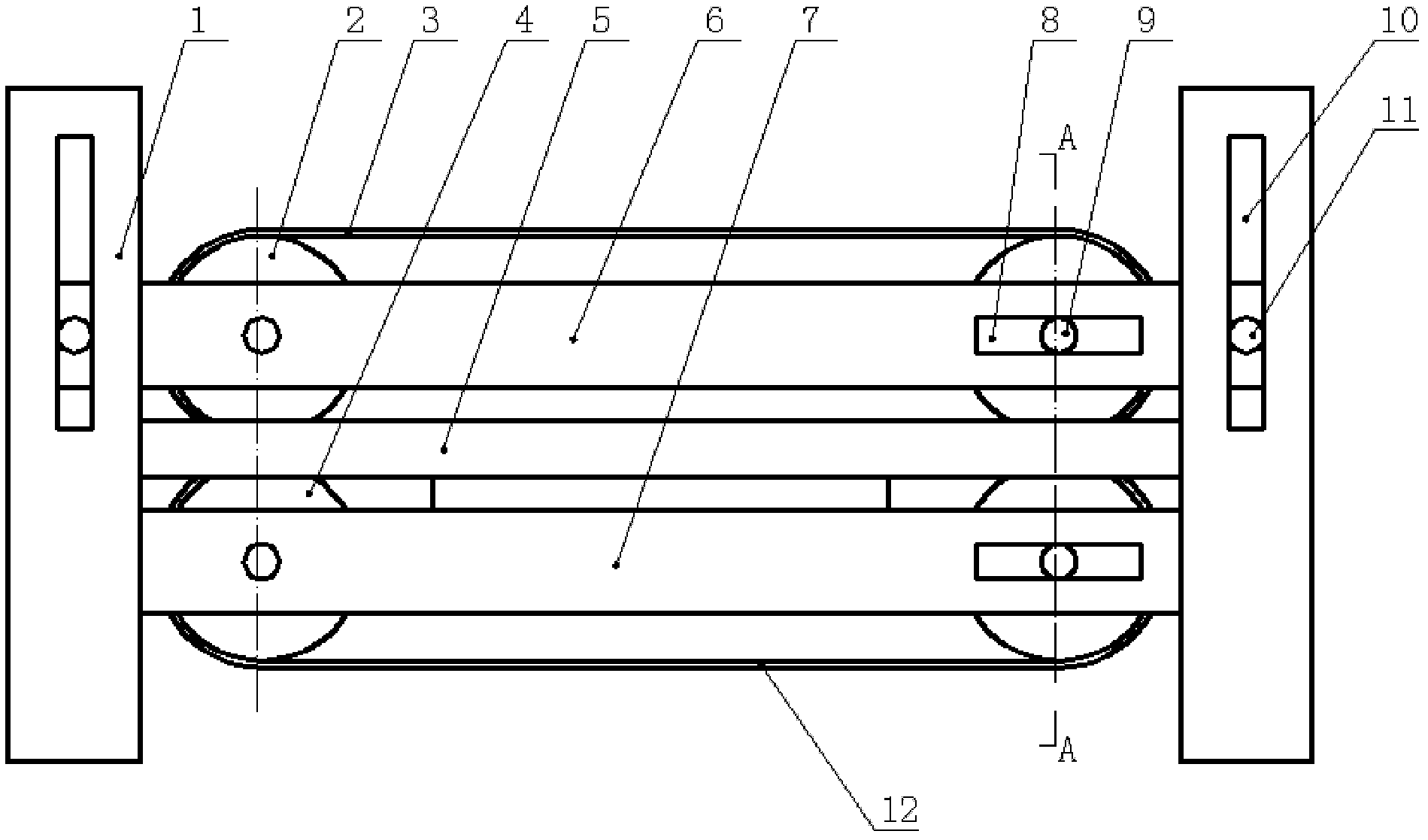
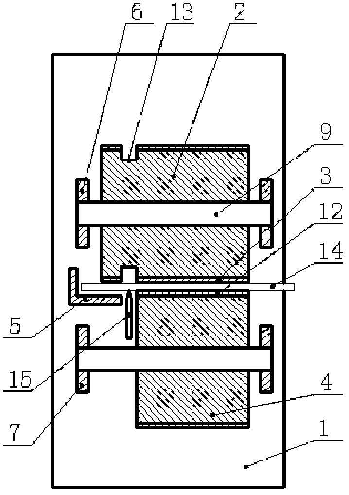
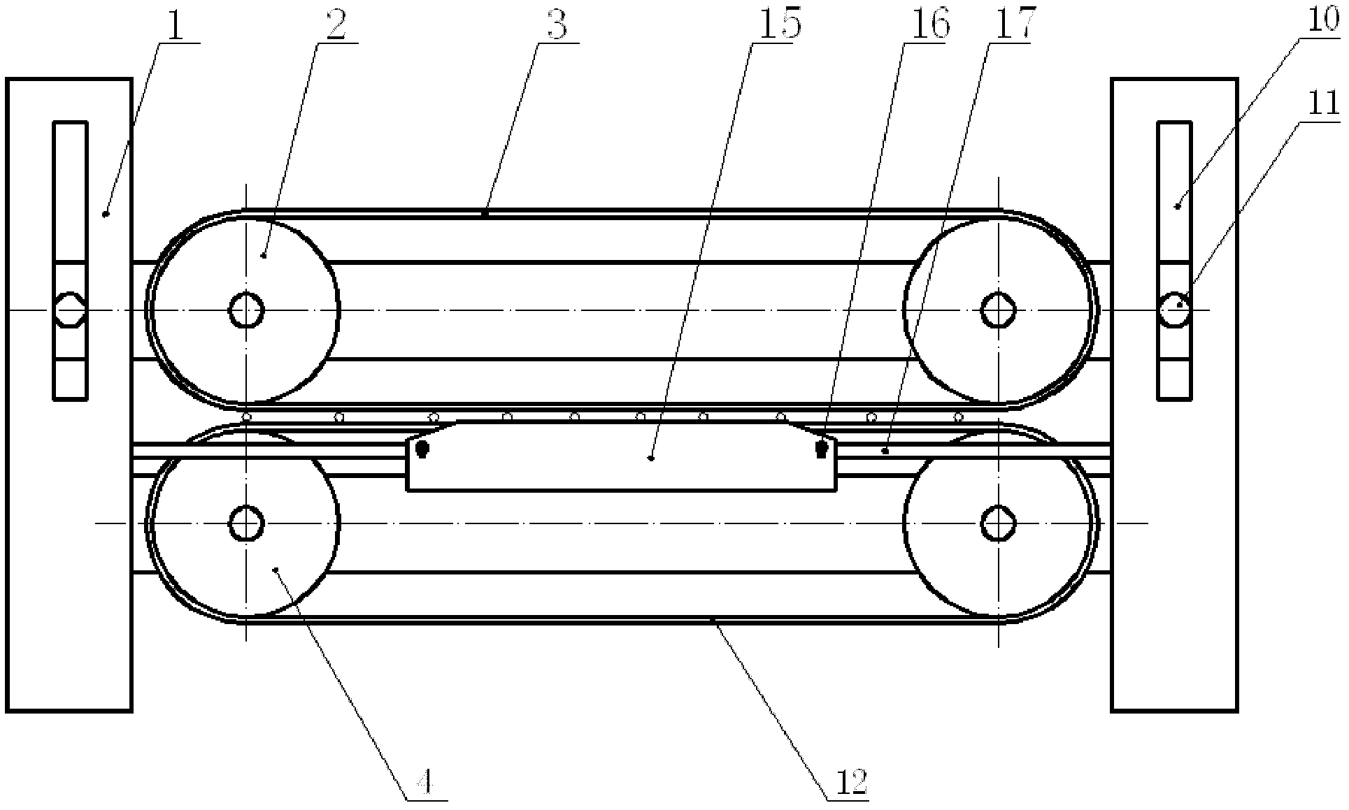
[0024] A semi-automatic ironing equipment, including two side stands 1, electric ironing knife 15, upper pulley group 2, lower pulley group 4, upper horizontal plate 6 and lower horizontal plate 7, and the upper and lower intervals are installed between the vertical stands on both sides The upper pulley set and the lower pulley set, the upper pulley set is installed on the vertical frames on both sides through the upper horizontal plates on the front and rear sides, and the lower pulley set is installed on the vertical frames on both sides through the lower horizontal plates on the front and rear sides There is a horizontal gap between the upper pulley group and the lower pulley group, and the lead wi...


PUM


Abstract

The invention relates to semi-automatic end scalding equipment which comprises two side vertical frames, an electric heating scalding tool, an upper belt pulley group, a lower belt pulley group, upper cross boards and lower cross boards. The upper belt pulley group and the lower belt pulley group are arranged up and down between the two side vertical frames at intervals. The upper belt pulley group is arranged on the two side vertical frames through the upper cross boards at both front and rear sides of the upper belt pulley group. The lower belt pulley group is arranged on the two side vertical frames through the lower cross boards at both front and rear sides of the lower belt pulley group. A horizontal gap is formed between the upper belt pulley group and the lower belt pulley group. The electric heating scalding tool is coaxially and fixedly arranged at the front side of the horizontal gap between the upper belt pulley group and the lower belt pulley group. The upper edge of the electric heating scalding tool is slightly higher than the upper plane of a lower belt. Due to the adoption of lead end scalding equipment which is disclosed by the invention, has scientific design and a reasonable structure, is simple and convenient to operate and is stabile and reliable, the processing efficiency can be effectively promoted, the labor intensity is reduced, the processing quality is improved, the material waste is avoided, operators keep away from harmful flue gas, the body health of the operators is protected and the damage is effectively avoided.

Description

technical field [0001] The invention belongs to the field of wire harness processing, and relates to a wire harness end processing device, in particular to a semi-automatic ironing device. Background technique [0002] During the processing of the lead wire harness of the enclosed motor, it is necessary to iron off the insulation layer at both ends of the lead wire according to the size requirements, one end is used for terminal crimping, and the other end is used for winding wiring. The current processing technology relies on manually rotating the lead wire on a fixed ironing knife to achieve the purpose of ironing the insulation layer of the end. The processing efficiency is low. During processing, the size and length of the processing part of the lead wire end must be manually determined, and the processing accuracy is affected by humans. Larger, repeating a single action for a long time is more likely to cause operational errors, such as the end of the lead wire of the n...

Claims


Application Information

Patent Timeline
Patent Type & Authority Applications(China)
IPC IPC(8): H01R43/28
Inventor 金捷张立国柴寿安
Owner TIANJIN HUAZHIYANG SPECIAL CABLE
Why Eureka
Try Eureka