Atomizer capable with nozzle and flow guide tube prevented from blockage

A technology of diversion tube and atomizer, which is applied in the field of atomizer, and can solve the problem of airflow atomization nozzle and diversion tube blocking the atomization process, affecting the atomized powder to achieve the ideal crushing effect, nozzle outlet and atomization point Long distance and other problems, to achieve the effect of eliminating low melting point blockage, reducing component pollution, and maintaining temperature

Active Publication Date: 2012-07-04
SHANGHAI LUOKE CENT CONTROLLED ENERGY SAVING TECH CO LTD
View PDF6 Cites 8 Cited by
  • Summary
  • Abstract
  • Description
  • Claims
  • Application Information

AI Technical Summary

Problems solved by technology

[0005] In the prior art, there are various structural forms of atomizers. According to the structure of the nozzle, it can be divided into annular hole type atomizer and annular slot type atomizer. During the process, nozzles and nozzles are often clogged, which is at least caused by the following reasons: first, the molten metal solidifies due to the temperature drop during the flow process; Intense cooling is generated at the port of the draft tube, so that the liquid flow solidifies and blocks the draft tube and the nozzle; the third is the negative pressure turbulent flow area under the draft tube, which causes the metal droplets to splash onto the nozzle port and cause blockage; the fourth is due to The metal droplets splash back during the atomization process, that is, the atomized droplets fly in the direction of the airflow atomization nozzle, and the splashed metal droplets adhere to the lower end of the airflow atomization nozzle, and continue to solidify and accumulate, eventually causing The atomization process is interrupted by the blockage of the air atomization nozzle and the guide tube
Production cannot continue once nozzles and nozzles are clogged
In this case, only the entire atomizer needs to be replaced, which greatly increases the production cost, and also affects the preparation efficiency and product quality
[0006] At present, there are many technologies for improving and updating the atomizer, and there are many related patents, but most of these technologies are related to how to control the particle size of metal powder and how to improve production efficiency. No. 201110452080.0 patent application mentioned a solution to the problem of atomizer clogging, but there is still a technical problem that the distance between the nozzle outlet and the atomization point is too long, which affects the atomized powder to achieve the ideal crushing effect, but the nozzle outlet is shortened The distance from the atomization point is likely to cause nozzle and guide tube blockage

Method used


Image

  • Atomizer capable with nozzle and flow guide tube prevented from blockage
  • Atomizer capable with nozzle and flow guide tube prevented from blockage

Examples


Embodiment 1

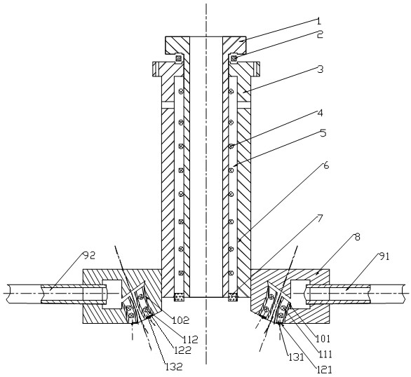
[0040] An atomizer that prevents nozzles and guide tubes from being clogged, its structural schematic diagram is shown in figure 1As shown, it consists of a guide tube 1, a nozzle 8, and also includes a metal jacket 3, a gap 5 between the guide tube 1 and the metal jacket 3, a heating element A4, a white reflective coating 6, a ceramic sealing ring 7, and a heating element B111 and B112, metal sealing rings 121 and 122, gasket 2.

[0041] The nozzle 8 is provided with two inlet pipes 91, 92 and two outlet pipes 101 and 102 of Laval structure, and the angle between the central axes of the two outlet pipes 101 and 102 of the nozzle is between 20° and 75°. Between the outlet pipes 101 and 102 of the two laval structures of the nozzle 8, gaps 131 and 132 are set at the periphery of 10mm~100mm, and heating elements B111 and B112 are installed inside the gaps 131 and 132, and the outlet pipes of the two laval structures of the nozzle The ends of the gaps 131 and 132 between 101 and...


PUM


Abstract

The invention discloses an atomizer with a nozzle and a flow guide tube prevented from blockage. The atomizer is composed of a flow guide tube, a metal jacket, a nozzle, a heating body A, a ceramic sealing ring, a metal sealing ring, a gasket and the like, wherein a gap between the flow guide tube and the metal jacket is provided with the heating body A; a heating body B is arrange each of gaps of the two Laval-structure air outlet tubes of the nozzle; the inner surface of the metal jacket is provided with a metal reflection film or a sprayed white reflection coating; the lower end part of the metal jacket and the lower end part of the flow guide tube are level; the end part of a gap between the lower end part of the metal jacket and the lower end part of the flow guide tube is sealed by the ceramic sealing ring; and the end parts of the gaps between the two Laval-structure air outlet tubes of the nozzle are in threaded connection and sealed by the metal sealing ring. The atomizer has the functions of effectively preventing metal and alloy from being blocked and solving the blockage problem, is suitable for melt flow guidance for metal or alloy atomization, has the advantages of simple structure and the like, and is convenient to install, and the production efficiency can be improved.

Description

technical field [0001] The invention relates to an atomizer which prevents nozzles and draft tubes from being clogged and which is used for producing superfine powders from gas atomized molten liquid. Background technique [0002] Gas atomization powder making is a powder making method that impacts liquid metal or alloy flow with high-speed airflow, breaks it into tiny liquid droplets, and then cools and solidifies into powder in the environment. Atomized powder has the advantages of high sphericity, low oxygen content and adaptability to the production of various metal and alloy powders. It has become the main development direction of high-performance and special alloy powder preparation technology. [0003] The whole process of atomization is extremely complicated, and the atomization effect is affected by many factors. The core of atomization technology is how to efficiently convert the kinetic energy of gas into the surface energy of atomized powder. The crushing degree...

Claims


Application Information

Patent Timeline
Patent Type & Authority Applications(China)
IPC IPC(8): B22F9/08
Inventor 江国健徐家跃
Owner SHANGHAI LUOKE CENT CONTROLLED ENERGY SAVING TECH CO LTD
Why Eureka
Try Eureka