Machining method for valve body, clamping clamp and machining equipment

A processing method and technology of processing equipment, used in metal processing equipment, manufacturing tools, metal processing, etc.

Active Publication Date: 2012-07-04
SHANGHAI HONGGONG MASCH TECH CO LTD
View PDF6 Cites 60 Cited by
  • Summary
  • Abstract
  • Description
  • Claims
  • Application Information

AI Technical Summary

Problems solved by technology

[0006] The technical problem to be solved by the present invention is to provide a method for completing all the processing procedures of the gate valve body in one clamping in order to solve the shortcomings of the current processing methods for parts such as the gate valve body whose processing surface is perpendicular to the same reference plane. processing methods

Method used


Image

  • Machining method for valve body, clamping clamp and machining equipment
  • Machining method for valve body, clamping clamp and machining equipment
  • Machining method for valve body, clamping clamp and machining equipment

Examples


Embodiment 1

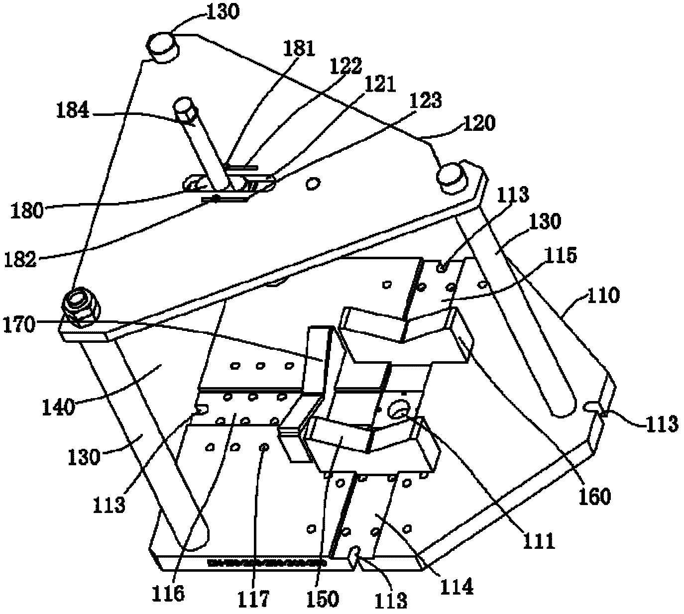
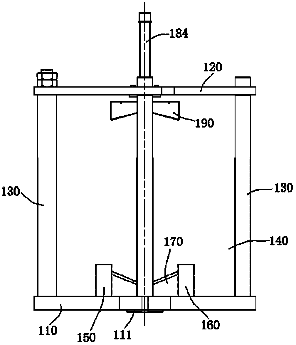
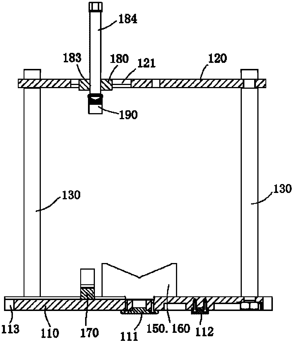
[0054] see Figure 1 to Figure 3 , the clamping fixture shown in the figure includes a bottom plate 110 and a top plate 120. The top plate 120 is installed on the bottom plate 110 through three rotating rods 130. Between the bottom plate 110 and the top plate 120, a multi-processing surface-type part that accommodates the same center of rotation is set. Space 140.

[0055]The bottom surface of the base plate 110 is provided with a central positioning block 111 cooperating with the central positioning hole of the rotary table, a positioning flat key 112 cooperating with the positioning groove on the rotary table, and several bolt opening slots 113 for clamping. On the front of the bottom plate 110, there are three T-shaped slots 114, 115, 116 radially distributed with the center of the center positioning block 111 as the center of the circle, and several T-shaped slots 114, 115, 116 are provided on both sides Bolt through hole 117; three T-shaped slots 114, 115, 116 are arrang...

Embodiment 2

[0058] see Figure 4 to Figure 6 The clamping fixture shown in the figure includes a rotating shaft 410, a pair of rigging parts 420, an I-beam part 430, a beam part 440, a disc jack assembly 450 and three V-shaped irons 460, 470, 480.

[0059] A rotating shaft positioning block 411 is fixed on the bottom of the rotating shaft 410, and the rotating shaft positioning block 411 is installed on the band end tooth positioning rotary table (not shown) by a T-shaped slot with a bolt 412 and a nut 413. A plurality of positioning holes 414 are arranged at intervals along the axial direction on the rotating shaft 410 .

[0060] The rotating shaft 410 and a pair of rigging parts 420 are arranged in a triangle on the rotary table with end teeth positioning to define a space 490 for accommodating the gate valve body 300; three V-shaped irons 460, 470, 480 are also used for T-shaped slots Bolts and nuts are installed on the rotary workbench with end tooth positioning. Three V-shaped irons...


PUM


Abstract

The invention discloses a machining method for a valve body. The valve body to be machined is horizontally clamped on a workpiece revolving platform of machining equipment by using a clamping clamp, and a plane to be machined of the valve body is adjusted to be perpendicular to the workpiece revolving platform of the machining equipment, so that an intersection point of a central axis of the plane to be machined of the valve body is overlapped with a revolving center of the workpiece revolving platform, and the machining method requires that an extension line of a central axis of a cutter revolving body of the machining equipment is intersected with that of the revolving central axis of the workpiece revolving platform; and after a machining part is machined, a next machining part can be machined every time when the workpiece revolving platform is turned for an angle. The invention also discloses the clamping clamp and the machining equipment for realizing the machining method. According to the machining method, the clamping clamp and the machining equipment, all machining can be finished with one person and one machine, so that the aims of reducing the clamping frequency, increasing the machining efficiency, reducing investment in human resources and reducing manufacturing cost of a product are fulfilled. The machining method can also be used for machining a part with a plurality of machining surface perpendicular to the same reference planes, and has broad universality.

Description

technical field [0001] The invention relates to a processing method for a valve body, a clamping fixture and processing equipment. Background technique [0002] Gate valve body, check valve body, ball valve body, straight stroke regulating valve body, straight stroke control valve body, plunger valve body, butterfly valve body, steam trap valve body, diaphragm valve body, etc. The valve bodies of all kinds of valves have a common characteristic, that is, each processing surface to be processed is perpendicular to a common datum plane. [0003] For valve body processing, at present, domestic and foreign valve manufacturers usually use ordinary lathes, drilling machines, boring machines or CNC lathes, CNC drilling machines, and CNC boring machines to process valve body parts. When these machine tools process the valve body, they first use a lathe or a CNC lathe to fix the flange at one end to turn the flange surface and water lines of the opposite flange at the other end, and...

Claims


Application Information

Patent Timeline
Patent Type & Authority Applications(China)
IPC IPC(8): B23Q7/02B23Q3/06B23Q37/00
Inventor 余长林孙茂滕金博凯
Owner SHANGHAI HONGGONG MASCH TECH CO LTD
Why Eureka
Try Eureka