On-line automatic tool setting and breakage detection device for minitype milling tool

An automatic tool setting and damage detection technology, which is applied in the direction of measuring/indicating equipment, metal processing machinery parts, metal processing equipment, etc., can solve the problems of size reduction, low reliability, and poor rigidity of micro tools, so as to prevent loss, Reliable measurement, fast detection of effects

Inactive Publication Date: 2012-07-04
SHANGHAI UNIV
View PDF4 Cites 50 Cited by
  • Summary
  • Abstract
  • Description
  • Claims
  • Application Information

AI Technical Summary

Problems solved by technology

[0003] Before micro-milling, it is necessary to determine the length and radius offset of the tool for tool setting. At present, on the micro-nano milling processing center, the laser tool setting system based on the principle of occlusion is usually used, because the size of the micro-milling cutter is greatly reduced. , the diffraction of light makes the measurement accuracy greatly reduced, so the repeatability of the measurement results is poor and the reliability is low
[0004] In addition, d

Method used


Image

  • On-line automatic tool setting and breakage detection device for minitype milling tool
  • On-line automatic tool setting and breakage detection device for minitype milling tool
  • On-line automatic tool setting and breakage detection device for minitype milling tool

Examples


Embodiment 1

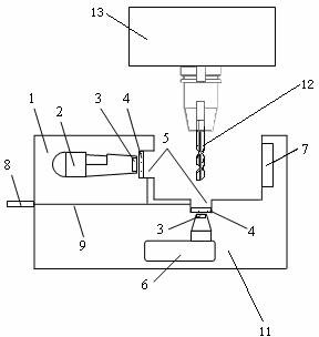
[0025] see figure 1 and figure 2 , an on-line automatic tool setting and damage detection device for micro milling cutters, comprising a housing 1, a device base 11, a tool optical detection system, a centralized control system and a tool wear alarm system, the device base 11 is fixedly installed on a machine tool with a tool 12 On the working table, the tool optical detection system is installed in the equipment cavity formed by the housing 1 and the device base 11. The tool optical detection system is fixed and installed on the device base 11 through the device bracket. The tool optical detection system is an area array image sensor system, the image data signal output end of the tool optical detection system is connected to the signal receiving end of the centralized control system, and the alarm command signal output end of the centralized control system is connected to the signal receiving end of the tool wear alarm system, which is characterized in that: the housing 1 ...

Embodiment 2

[0039] The technical solution of this embodiment is basically the same as that of Embodiment 1, the difference is that:

[0040] In this embodiment, the diffuse reflection backlight light source 7 is a strobe light source. Because the rotation speed of the micro milling cutter is very fast, the diffuse reflection backlight light source 7 can adopt a strobe light source to ensure that the image has good clarity.

Embodiment 3

[0042] The technical solutions of this embodiment are basically the same as those of Embodiment 1 and Embodiment 2, except that:

[0043] In this embodiment, the ring light source 3 is a strobe light source. Since the rotation speed of the micro-milling cutter is very fast, the ring light source 3 can adopt a stroboscopic light source to further ensure that the image has good clarity.


PUM


Abstract

The invention discloses an on-line automatic tool setting and breakage detection device for a minitype milling tool. The device comprises a shell, a device base, an optical tool detection system, a centralized control system and a tool abrasion alarming system, wherein the optical tool detection system is fixedly installed on the device base by a device bracket; the optical tool detection system is a planar-array type image sensor system and is in signal connection with the centralized control system; the centralized control system is in signal connection with the tool abrasion alarming system; the optical tool detection system comprises a radial tool measurement device and a tool end measuring device; the radial tool measurement device collects the local detailed image data of a cutting blade abrasion zone along the radial direction of the tool to realize automatic tool setting and breakage detection; and the tool part measuring device assists the breakage detection of the tool; and the main shaft of the machine tool of the tool is provided with a calibrated target object. The detection device is characterized in that the radius and length offset of the tool can be automatically measured when the tool rotates and the breakage situation of the minitype milling tool can be detected.

Description

technical field [0001] The invention relates to a mechanical processing detection device, in particular to an automatic tool setting and damage detection device for milling cutters. Background technique [0002] Micro-milling is an important method of ultra-precision machining, which can flexibly process structures with three-dimensional micro-sizes. Micro-milling cutters are a key part of micro-milling processing systems. [0003] Before micro-milling, it is necessary to determine the length and radius offset of the tool for tool setting. At present, on the micro-nano milling processing center, the laser tool setting system based on the principle of occlusion is usually used, because the size of the micro-milling cutter is greatly reduced. , the diffraction of light makes the measurement accuracy greatly reduced, so the repeatability of the measurement results is poor and the reliability is low. [0004] In addition, due to the poor rigidity of micro-tools, they are prone ...

Claims


Application Information

Patent Timeline
IPC IPC(8): B23Q17/09B23Q17/22B23Q17/24
Inventor 张曦李来维程方
Owner SHANGHAI UNIV
Why Eureka
Try Eureka