Method for manufacturing scraping knife

A manufacturing method and scraper technology, applied in the field of parts and components, can solve the problems of numerous scraper production processes, affecting the quality of scraper powder control, and reducing scraper flatness, etc., so as to reduce the production process, reduce the cost of production raw materials, and reduce the effect of the process.

Inactive Publication Date: 2012-07-04
PRINT RITE UNICORN IMAGE PROD CO LTD
View PDF4 Cites 4 Cited by
  • Summary
  • Abstract
  • Description
  • Claims
  • Application Information

AI Technical Summary

Problems solved by technology

In the production process of the strip-type scraper, the glue used to bond the strip and the metal knife holder is a toxic glue that emits a pungent smell. Long-term contact with the glue will cause harm to the human body.
In additi...

Method used


Image

  • Method for manufacturing scraping knife
  • Method for manufacturing scraping knife
  • Method for manufacturing scraping knife

Examples


no. 1 example

[0035] Scraper production method steps

[0036] 1) Mold preparation

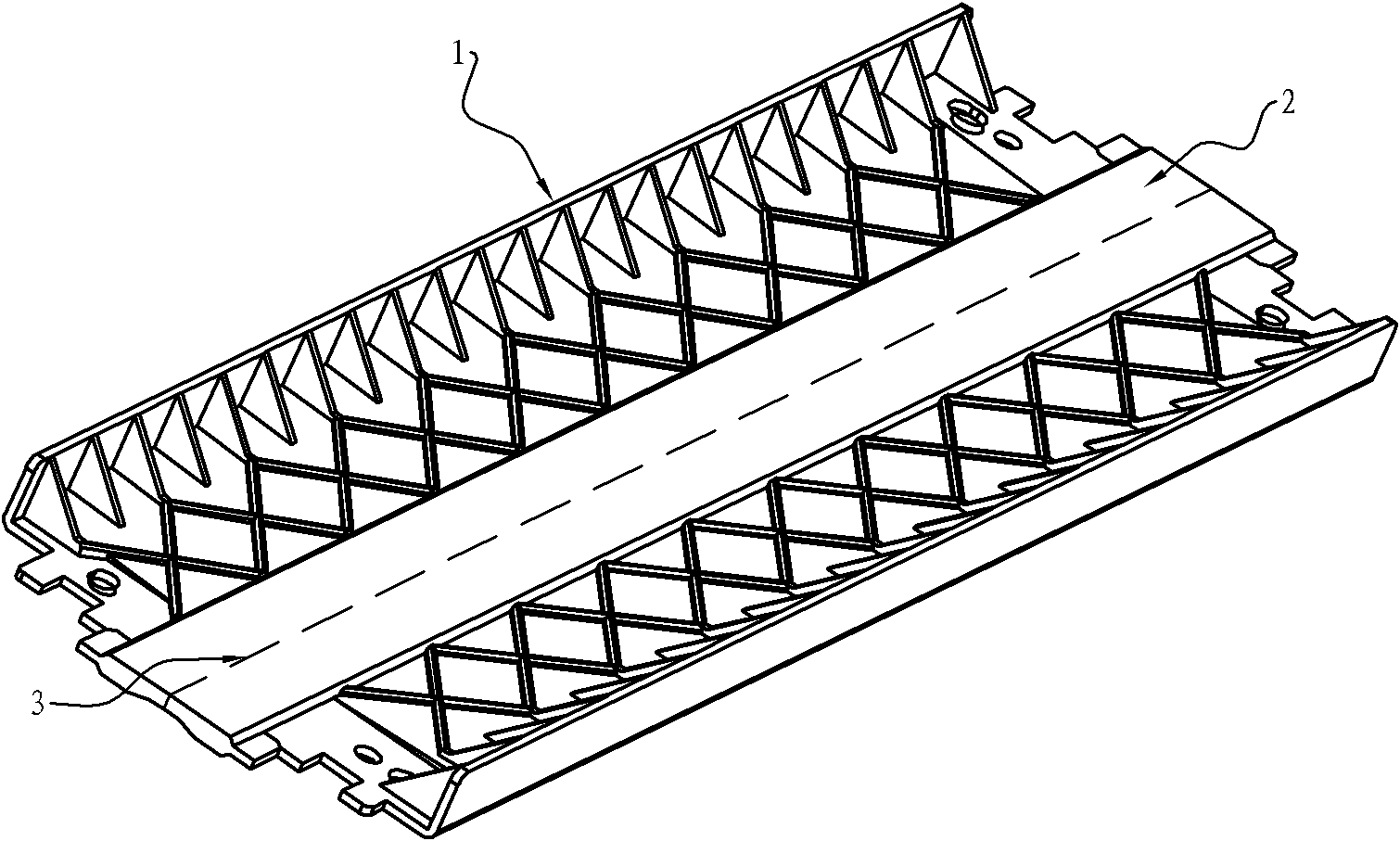
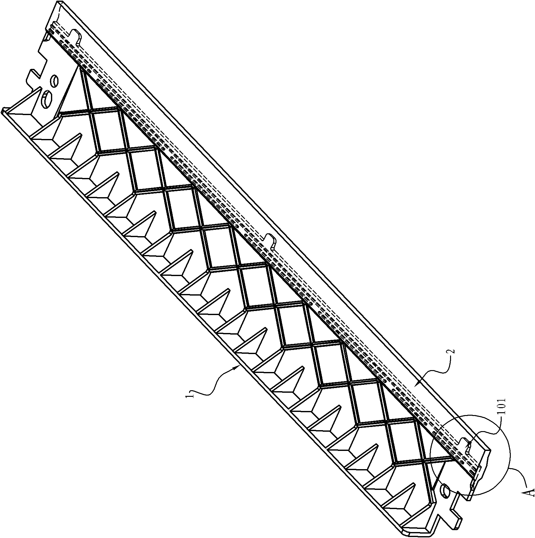
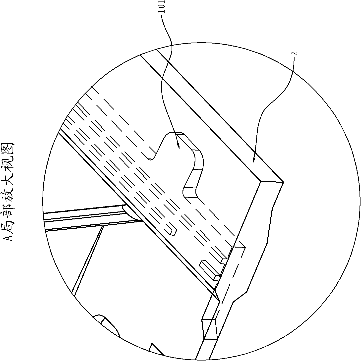
[0037] The mold of the clamping device is in accordance with figure 1 The structural design of two connected scrapers is shown. figure 1 The two scrapers shown in have the same structure, the edges 3 of the blades 2 of the two scrapers are aligned and connected together, the parallel blades 2 are located on the same plane, and the supporting end of each blade holder 1 is bent toward the same side of the blade 2 . The mold core on the movable mold and the fixed mold encloses two connected blade mold cavities and two knife holder mold cavities, wherein a movable mold core on the fixed mold fills the two connected blade mold cavities.

[0038] 2) Feeding

[0039] Add hard rubber to the hopper of the main injection device of the dual-material injection molding machine. The hard rubber can be glass fiber reinforced polyphenylene sulfide (PPS+GF), glass fiber reinforced polycarbonate (PC+GF) or polyparaphenyle...

no. 2 example

[0055] Scraper production method steps

[0056] 1) Mold preparation

[0057] Make a scraper mold, including a blade cavity and a knife holder cavity, the blade cavity and the knife holder cavity are surrounded by the movable mold of the mold and the core on the fixed mold, and there is a movable mold on the fixed mold The core fills the insert cavity.

[0058] 2) Feeding

[0059] Add hard rubber to the hopper of the main injection device of the dual-material injection molding machine. The hard rubber can be glass fiber reinforced polyphenylene sulfide (PPS+GF), glass fiber reinforced polycarbonate (PC+GF) or polyparaphenylene Any of butylenedicarboxylate (PBT). At the same time, add soft rubber to the hopper of the auxiliary injection device of the double-material injection molding machine. The soft rubber can be thermoplastic polyurethane elastomer (TPU) or polyamide resin (PA).

[0060] 3) Set injection molding parameters and inject a scraper

[0061] The parameter sett...


PUM


Abstract

The invention provides a method for manufacturing a scraping knife. The scraping knife comprises a knife rest made of ebonite and a blade made of soft rubber. The method for manufacturing the scraping knife comprises the following steps of: preparing a die; adding the ebonite and the soft rubber; performing injection molding of the knife rest; performing the injection molding of the blade; and demolding. According to the method, the full-plastic scraping machine is produced by using a double-material injection molding machine, so that the cost of production raw materials is reduced, production processes are reduced, the planeness of the scraping knife is improved, namely the quality of products is improved, and environmental pollution caused by the conventional process for manufacturing the scraping knife is avoided.

Description

technical field [0001] The present invention relates to the parts of electrophotographic image forming equipment, especially the manufacturing method of the scraper in the process box of the electrophotographic equipment. Background technique [0002] An electrophotographic image forming apparatus is an apparatus that forms an image on a recording material using an electrophotographic image forming process, and includes an electrophotographic copier, an electrophotographic printer, an electrophotographic printing facsimile, and the like. A process cartridge used in an electrophotographic image forming apparatus using an electrophotographic image forming process, is a unit cartridge including at least a developing roller as developing means and an electrophotographic photosensitive drum, the process cartridge can be detachably mounted to the main body of the electrophotographic image forming apparatus superior. [0003] A typical electrophotographic imaging device is a laser...

Claims


Application Information

Patent Timeline
IPC IPC(8): B29C45/03B29C45/32B29C45/78B29C45/77G03G15/08G03G21/00
CPCB29C45/77B29C45/1676G03G15/08B29L2031/7202B29C45/78B29C45/32G03G21/00B29C45/03G03G15/0812G03G21/0017
Inventor 宋道权
Owner PRINT RITE UNICORN IMAGE PROD CO LTD
Why Eureka
Try Eureka