Power battery system and control method

A technology of a power battery and a control method, which is applied in the field of vehicles, can solve the problems of shortening the life of the power battery 130, and achieve the effect of increasing the service life

Active Publication Date: 2012-07-04
CHERY AUTOMOBILE CO LTD
View PDF6 Cites 13 Cited by
  • Summary
  • Abstract
  • Description
  • Claims
  • Application Information

AI Technical Summary

Problems solved by technology

Since the power battery 130 in the prior art will be frequently charged and discharged when the extended-range electric vehicle is running, and most of the charging and discharging process is not a complete charging process and discharging process, the life of the power battery 130 will be greatly shortened. reduce

Method used


Image

  • Power battery system and control method
  • Power battery system and control method
  • Power battery system and control method

Examples


Embodiment 1

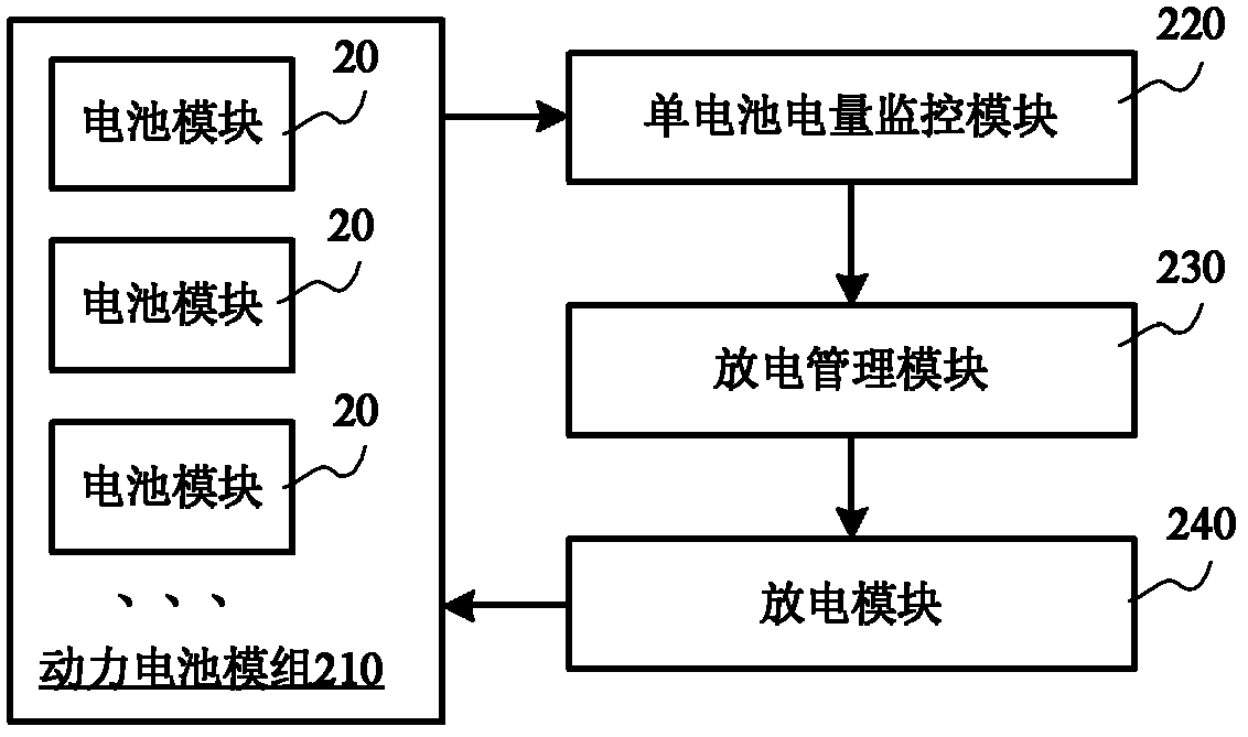
[0045] Please refer to figure 2 , which shows a structural block diagram of the power battery system provided by Embodiment 1 of the present invention. The power battery system can be used for extended-range electric vehicles, and the power battery system includes a power battery module 210 , a battery power monitoring module 220 , a discharge management module 230 and a discharge module 240 .

[0046] The power battery module 210 includes several battery modules 20 . The several battery modules may be at least two battery modules. The several battery modules 20 can also be the same battery modules, that is, the several battery modules 20 can all have the same output voltage, output current, charging voltage, charging current, total voltage, battery capacity and other parameters. Battery pack. The output voltage of each battery module 20 can be the working voltage required by the motor.

[0047] The battery power monitoring module 220 is used to monitor the power state of...

Embodiment 2

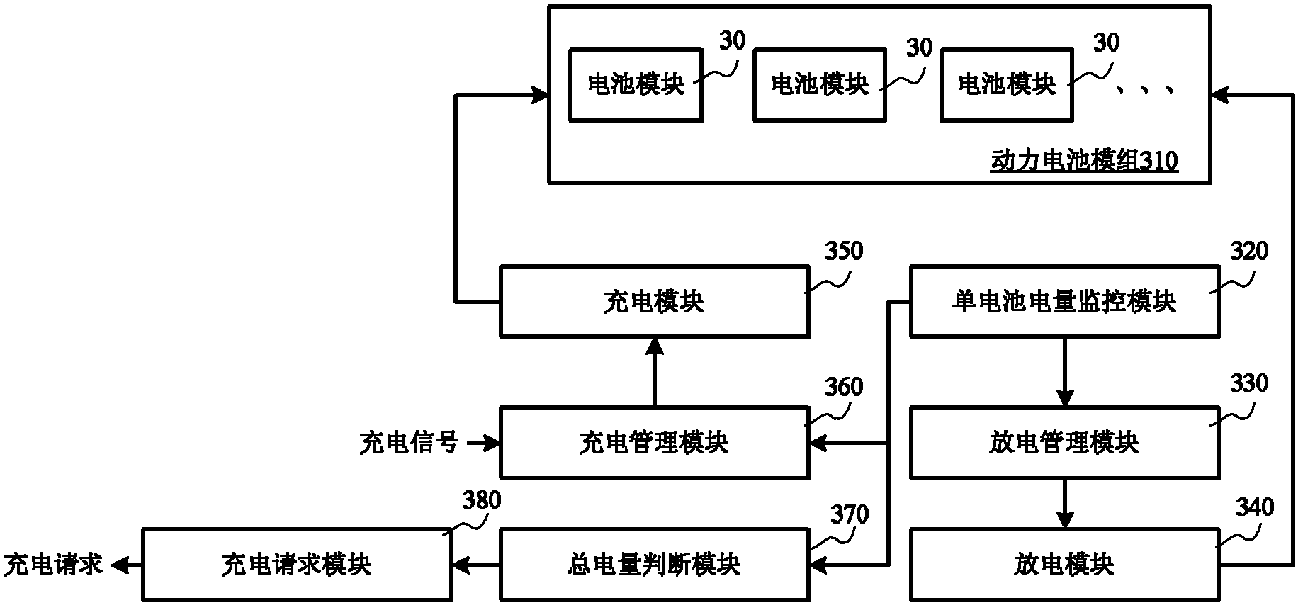
[0052] Please refer to image 3 , which shows a structural block diagram of the power battery system provided by Embodiment 1 of the present invention. The power battery system can be used for extended-range electric vehicles. The power battery system includes a power battery module 310, a single battery power monitoring module 320, a discharge management module 330, a discharge module 340, a charge management module 350, a charge module 360, and The battery capacity judgment module 370 and the charging request module 380 .

[0053] The power battery module 310 includes several battery modules 30 . The several battery modules may be at least two battery modules. The several battery modules 30 can also be the same battery modules, that is, the several battery modules 30 can all have the same output voltage, output current, charging voltage, charging current, total voltage, battery capacity and other parameters. Battery pack. The output voltage of each battery module 30 can ...

Embodiment 3

[0063] Please refer to Figure 4 , which shows a method flowchart of the control method provided by Embodiment 3 of the present invention. The control method can be used in a power battery system including multiple battery modules, and the control method includes:

[0064] Step 401, monitoring the power state of each battery module, the power state includes a fully charged state, a partially charged state and an empty state;

[0065] Step 402, put the battery module whose power state changes from a non-full charge state to a full charge state into a sequence to be discharged;

[0066] Step 403, when the discharge signal is received, the battery modules in the sequence to be discharged are discharged sequentially.

[0067] Specifically, discharging the battery modules in the sequence to be discharged sequentially includes: after the power state of the battery module currently being discharged changes from a non-full state to an empty state, stopping the discharge of the batte...


PUM


Abstract

The invention discloses a power battery system and a control method, and belongs the field of vehicles. The power battery system comprises a power battery module, a single battery electric quantity monitoring module, a discharge management module and a discharge module, wherein the power battery module comprises a plurality of battery modules; the single battery electric quantity monitoring module is used for monitoring the electric quantity state of each battery module, and the electric quantity state comprises a full power state, a non-full power state and a power-null state; the discharge management module is used for putting the battery modules of which the electric quantity state is changed into the full power state from the non-full power state into a to-be-discharged sequence; and the discharge module is used for allowing the battery modules in the to-be-discharged sequence to be discharged sequentially when a discharge signal is received. According to the power battery system, the service life of the battery modules can be prolonged effectively by arranging the power battery module with the battery modules and controlling the single battery module to always complete an integral charging or discharging process.

Description

technical field [0001] The invention relates to the field of vehicles, in particular to a power battery system and a control method for an extended-range electric vehicle. Background technique [0002] A range-extended electric vehicle is an electric vehicle with a range extender added on the basis of a pure electric vehicle. The range extender can be a generator set powered by a fuel or gas engine. Extended-range electric vehicles have the advantages of long mileage, easy maintenance and good energy saving and emission reduction. [0003] Please refer to figure 1 , which shows a structural principle diagram of a range-extended electric vehicle in the prior art. The range-extended electric vehicle includes a fuel or gas engine 110 , a generator 120 , a power battery 130 , an electric motor 140 and wheels 150 . The extended-range electric vehicle includes two working modes: the first working mode is a pure electric working mode, when the power battery 130 is fully charged,...

Claims


Application Information

Patent Timeline
IPC IPC(8): B60L11/12B60L11/18H02J7/00B60L50/15
CPCY02T10/7077Y02T10/7005Y02T10/70
Inventor 杨林
Owner CHERY AUTOMOBILE CO LTD
Why Eureka
Try Eureka