Air-powered braking roof wing device

An aerodynamic braking and wind wing technology, which is applied in the directions of brakes, braking components, vehicle parts, etc., can solve the problems of inability to withstand large wind forces, low driving requirements for wind blades, and unstable rotation of wind blades. The effect of safe work

Active Publication Date: 2012-07-04
华伍轨道交通装备(上海)有限责任公司 +1
View PDF6 Cites 10 Cited by
  • Summary
  • Abstract
  • Description
  • Claims
  • Application Information

AI Technical Summary

Problems solved by technology

For example, the Chinese patent "Electric Vehicle Brake Wind Foil System" (Patent No.: 200420092575.2), the disclosed wind blade is used on electric vehicles, and the speed of electric vehicles is relatively low

Method used


Image

  • Air-powered braking roof wing device
  • Air-powered braking roof wing device
  • Air-powered braking roof wing device

Examples


Embodiment Construction

[0034] The specific implementation of the aerodynamic brake roof wind wing device of the present invention will be described in detail below in conjunction with the accompanying drawings.

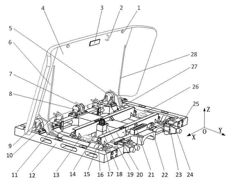
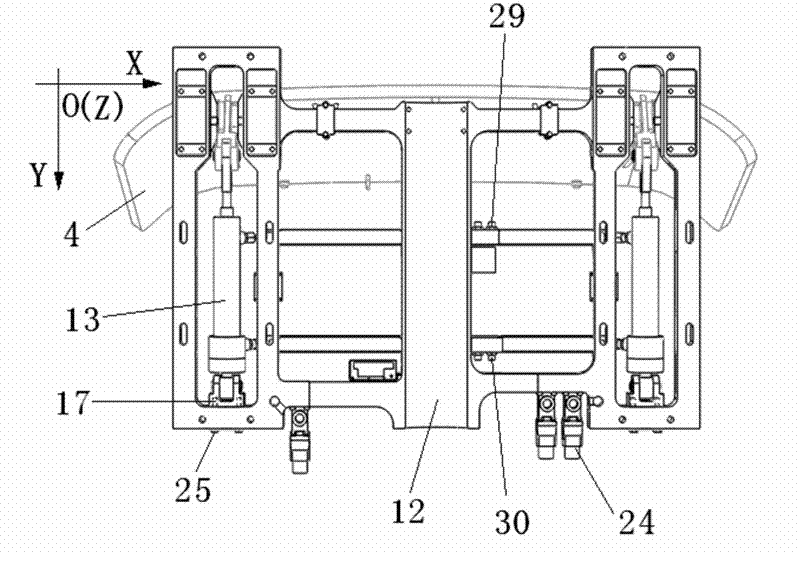
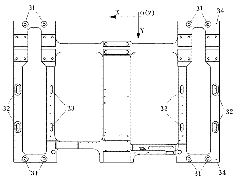
[0035] In order to make the present invention easy to understand, some directional terms are used in this specification. It should be noted that the directional terms mentioned in this specification, such as "up", "down", "left", "right", "front", "rear", etc., refer to the direction of the drawings, and The XYZ coordinate system in the drawings is for reference, the positive direction of the Z axis is set to "up", the negative direction of the Z axis is set to "down", the positive direction of the X axis is set to "left", and the negative direction of the X axis is set to "right". The positive direction of the Y axis is set to "back", and the negative direction of the Y axis is set to "front". The directional terms used are used to illustrate and understand the present invention, but not ...


PUM


Abstract

The invention discloses an air-powered braking roof wing device, which comprises a wing plate and a mounting connecting portion. The mounting connecting portion is connected with a roof, a rotary supporting portion and a hydraulic driving portion are disposed on the mounting connecting portion, the wing plate consists of a left rocker arm and a right rocker arm, the rotary supporting portion consists of a left rocker arm support and a right rocker arm support, the left rocker arm and the right rocker arm of the wing plate are respectively mounted on the left rocker arm support and the right rocker arm support of the rotary supporting portion, the hydraulic driving portion comprises hydraulic cylinders and hydraulic units, the hydraulic cylinders are connected to the hydraulic units by hydraulic pipes and joints, the hydraulic cylinders are mounted on the mounting connecting portion by hydraulic cylinder mounting seats, piston rods of the hydraulic cylinders are connected with the wing plate, the hydraulic units can drive the piston rods of the hydraulic cylinders to expand and retract, and accordingly, the wing plate is driven to rotate around the left rocker arm support and the right rocker arm support. The air-powered braking roof wing device with the structure is stable in opening and closing and fine in safety.

Description

technical field [0001] The invention relates to a train brake device, in particular to an aerodynamic brake roof wind wing device. Background technique [0002] Existing roof wind wing device generally comprises the wind wing plate that metal material is made and power mechanism, and power mechanism all adopts gear transmission to promote support bar to make wind wing plate turn over and put down. For example, the Chinese patent "Electric Vehicle Brake Wind Foil System" (Patent No.: 200420092575.2), the disclosed wind blade is used on electric vehicles, and the speed of electric vehicles is relatively low (compared with high-speed trains), so the wind The driving requirements of the flaps are also low, and there are problems such as the wind flaps are not rotating smoothly and cannot withstand large wind forces. Contents of the invention [0003] The object of the present invention is to solve the above-mentioned technical problems, and provide an aerodynamic brake roof w...

Claims


Application Information

Patent Timeline
IPC IPC(8): B60T1/16
Inventor 吴萌岭倪成权姚雪荣曾宪华
Owner 华伍轨道交通装备(上海)有限责任公司
Why Eureka
Try Eureka