Torque coordinated control method and torque coordinated control system for hybrid electric vehicle

A hybrid electric vehicle and power system technology, applied in the field of hybrid electric vehicle torque coordination control method and system, can solve the problems of slow torque response speed, slippage, fuel consumption and emission increase, etc. The effect of improving safety and economy

Active Publication Date: 2012-07-04
CHONGQING CHANGAN AUTOMOBILE CO LTD
View PDF5 Cites 23 Cited by
  • Summary
  • Abstract
  • Description
  • Claims
  • Application Information

AI Technical Summary

Problems solved by technology

[0004] But through the research of prior art, the inventor finds: although the hybrid electric vehicle adopts the same torque control method as the traditional vehicle and can basically meet the control demand of increasing torque, there are many deficiencies in the use process: one: due to the characteristics of the engine itself , the torque response speed is slow, and slippage may still occur in the process of meeting the torque increase demand; 2. Due to the rapid response to the torque increase demand, the combustion quality of the fuel engine will decline, which will bring about fuel consumption and emissions. Increase

Method used


Image

  • Torque coordinated control method and torque coordinated control system for hybrid electric vehicle
  • Torque coordinated control method and torque coordinated control system for hybrid electric vehicle
  • Torque coordinated control method and torque coordinated control system for hybrid electric vehicle

Examples


Embodiment 1

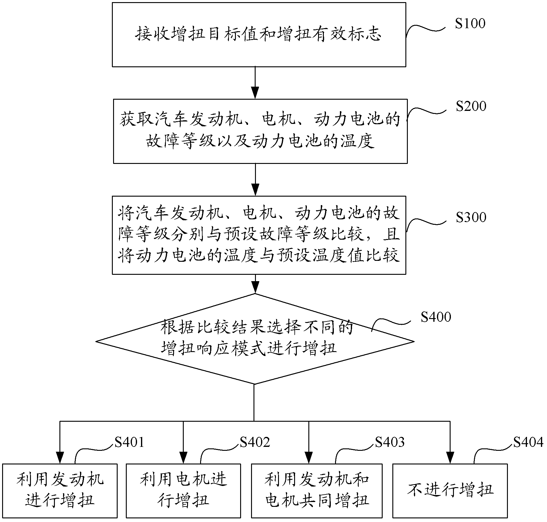
[0066] The motor failure level is 3, the battery failure level is 1, the engine failure level is 1, and the battery temperature is 20 degrees Celsius. According to the definition of the torque increase response mode conditions in the above method, the torque increase response mode in which the engine works alone should be used, and then the torque increase target value Tq_ESP_Increase and the torque increase valid flag Flag_Tq_Increase_Valide received from the bus are sent to the ECU, and the ECU controls The engine achieves torque increase, and at the same time sends a zero torque command to the IPU, and the motor does not generate torque during this process.

Embodiment 2

[0068] The motor fault level is 1, the battery fault level is 1, the engine fault level is 3, and the battery temperature is 20 degrees Celsius. According to the definition of the torque increase response mode conditions in the above method, the torque increase response mode in which the motor works alone should be used, and then the torque increase target value Tq_ESP_Increase and the torque increase valid flag Flag_Tq_Increase_Valide received from the bus are sent to the IPU, and the IPU controls The motor realizes the torque increase, and at the same time sends the torque command to the ECU during the normal sliding process, and the ECU still maintains the previous control mode during this process.

Embodiment 3

[0070] The motor failure level is level 1, the battery failure level is level 1, the engine failure level is level 1, and the battery temperature is 20 degrees Celsius. According to the definition of each torque increase response mode in the above method, the combined torque increase response mode should be used. First, the torque increase target value Tq_ESP_Increase and the torque increase valid flag Flag_Tq_Increase_Valide received from the bus are sent to the IPU, and the IPU controls the motor to realize the increase. After the preset time t, if there is still a torque increase demand, then the torque increase target value Tq_ESP_Increase and the torque increase valid flag Flag_Tq_Increase_Valide received from the bus are sent to the ECU, and at the same time a zero torque command is sent to the IPU, the motor does not Torque is generated again.


PUM


Abstract

The invention discloses a torque coordinated control method and a torque coordinated control system for a hybrid electric vehicle. The method includes the steps: receiving a torque increase target value and a torque increase effective sign; acquiring failure levels of an engine, a motor and a power battery of the vehicle and the temperature of the power battery; comparing the failure levels of the engine, the motor and the power battery of the vehicle with preset failure levels, and comparing the temperature of the power battery with a preset temperature value; and increasing torque by selecting different torque increase response modes according to comparison results. As compared with the prior art, when the torque needs to be increased during slippage of the vehicle, torque of the engine and torque of the motor can be controlled in a coordinated manner, and the shortcomings of an existing control method can be improved, so that the requirements of a vehicle stability control system on torque increase are met. Besides, by the aid of the method, driving comfortableness, safety and economy can be improved, and emission is reduced.

Description

technical field [0001] The present application relates to the technical field of automobiles, in particular to a torque coordination control method and system for a hybrid electric vehicle. Background technique [0002] When the vehicle is running on a road with a small adhesion coefficient (such as icy or water-filmed roads), if the driver does not step on the accelerator and brake, the vehicle will be in a coasting state. The vehicle generates braking force, also known as engine braking. In addition, when a large braking force is required such as downhill, the use of engine braking can reduce the burden on the wheel brakes and play a positive role in vehicle safety. [0003] However, when sliding on icy or low-adhesion roads with water film, even if there is only engine braking force at certain times, the wheels will lock up and slip due to excessive braking force, which is very dangerous. At present, the existing vehicle stability control system will detect the above si...

Claims


Application Information

Patent Timeline
Patent Type & Authority Applications(China)
IPC IPC(8): B60W30/188B60W20/00B60W10/06B60W10/08B60W20/10B60W20/40B60W20/50
CPCY02T10/6286Y02T10/62
Inventor 严钦山刘杰洪木南李宗华苏岭
Owner CHONGQING CHANGAN AUTOMOBILE CO LTD
Why Eureka
Try Eureka