
Blast-furnace gas pressure regulating process

A technology of pressure regulation and blast furnace gas, which is applied in blast furnace details, blast furnaces, furnaces, etc., can solve the problems of large noise and vibration of the airflow impacting the valve plate, affecting the normal production of the blast furnace, and unstable equipment operation, so as to achieve stable equipment operation and equipment The operation is simple and reliable, and the effect of saving and creating efficiency

Active Publication Date: 2012-07-04
鞍钢集团工程技术有限公司
View PDF3 Cites 1 Cited by
  • Summary
  • Abstract
  • Description
  • Claims
  • Application Information

AI Technical Summary

Problems solved by technology

[0002] The traditional blast furnace gas pressure adjustment process is realized by using multiple electric butterfly valves and a normal pipe. The defects of this process are: first, the equipment structure is complicated, because the number and specifications of the valves are determined according to the diameter of the main gas pipe, such as ф1500~ф2500 The diameter of the gas pipe needs to be equipped with 4 to 5 valves; the second is that the operation and control are complicated, one of the butterfly valve groups is controlled by an electric actuator, and the rest are operated remotely by electric motors in the operating room
The third is that the noise and vibration generated by the impact of the airflow on the valve plate are large, and the operation of the equipment is unstable.
Fourth, the safety and reliability are poor. Due to the impact of the air flow on the valve body, the sealing packing is worn away, and the probability of gas leakage is high.
In addition, Anshan Iron and Steel Blast Furnace uses two gas pressure regulating valves in parallel to realize the automatic adjustment of gas pressure. The defect of this process is that the noise and vibration are large. Within the normal range of furnace top pressure, the noise generated by the pressure reducer equipment has far exceeded the standard value, especially It is the vibration that affects the normal production of the blast furnace

Method used


Image

  • Blast-furnace gas pressure regulating process
  • Blast-furnace gas pressure regulating process
  • Blast-furnace gas pressure regulating process

Examples


Embodiment Construction

[0012] The present invention will be further described below in conjunction with accompanying drawing.

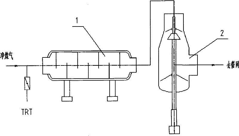
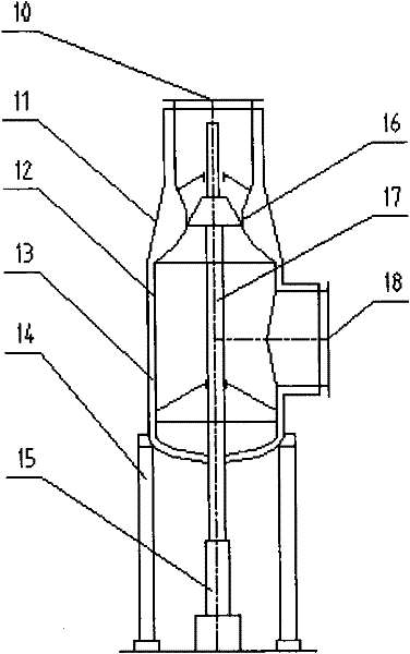
[0013] Such as Figure 1~3 As shown, the blast furnace gas pressure regulation process is mainly composed of pipelines and pressure reducer groups. The main clean gas pipeline is connected to the inlet of the first-stage pressure reducer 1, and the outlet of the first-stage pressure reducer is connected to the second-stage pressure reducer 2 through the pipeline. The inlets are connected, and the outlet of the second-stage pressure reducer is connected to the gas pipeline network through pipelines.

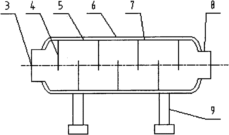
[0014] The first stage pressure reducer is a clapboard type, mainly composed of an inlet pipe 3, an outlet pipe 8, an inner shell 5, an outer shell 6, and a clapboard 4, and the inner and outer shells are filled with sound-absorbing materials 7, and the clapboard pressure reducer consists of Bearing 9 bears the weight and is installed horizontally.

[0015] The second-stage p...


PUM


Abstract

The invention provides a blast-furnace gas pressure regulating process, wherein a pipeline and a pressure reducer set are comprised. The pressure reducer set is formed by connecting two stages of pressure reducers in series. The first stage of pressure reducer is of a clapboard type, has a fixed pressure reducing value and mainly comprises an inlet pipeline, an outlet pipeline, an inner shell, anouter shell, a sound attenuation material, a clapboard and a support. The second stage of pressure reducer is of a circular seam type, has an adjustable pressure reduction value and mainly comprises an outlet pipeline, an inlet pipeline, an inner shell, an outer shell, a clock valve body, a sound attenuation material, a seal ring, a transmission device, a support device and the like. According tothe blast-furnace gas pressure regulation process, because the novel pressure redactor set which formed by connecting two stages of novel pressure reducers in series and completely different from a butterfly valve set manufactured by the traditional process, the adverse factors of the butterfly valve set are eliminated. The blast-furnace gas pressure regulating process disclosed by the invention has the advantages of concise flow, simple and reliable equipment operation, low noise, low vibration, guarantee of stable equipment operation, prolonged service life, simple structure of equipment, investment saving, low routine maintenance and considerable benefit saving.

Description

technical field [0001] The invention relates to a process for adjusting blast furnace gas pressure, in particular to a process for automatically adjusting blast furnace gas pressure by using a pressure reducer. Background technique [0002] The traditional blast furnace gas pressure adjustment process is realized by using multiple electric butterfly valves and a normal pipe. The defects of this process are: first, the equipment structure is complicated, because the number and specifications of the valves are determined according to the diameter of the main gas pipe, such as ф1500~ф2500 The gas pipe with the pipe diameter needs to be equipped with 4 to 5 valves; the second is that the operation and control are complicated, one of the butterfly valve groups is controlled by an electric actuator, and the rest are operated remotely by electric motors in the operating room. The third is that the noise and vibration generated by the impact of the air flow on the valve plate are la...

Claims


Application Information

Patent Timeline
Patent Type & Authority Applications(China)
IPC IPC(8): C21B5/06
Inventor 陈兴家魏成智尚策苏蔚李霞张守奎赵晓峰
Owner 鞍钢集团工程技术有限公司
Learn More