Density triangular adjusting mechanism of computer flat knitting machine

A technology of density triangle and adjustment mechanism, which is applied in knitting, weft knitting, textiles and papermaking, etc. It can solve the problems of increased manufacturing, high error probability, and complex structure, so as to reduce power consumption, avoid error probability, and embody economy sexual effect

Inactive Publication Date: 2012-07-04
JIANGSU JINLONG TECHNOLOGY CO LTD
View PDF5 Cites 1 Cited by
  • Summary
  • Abstract
  • Description
  • Claims
  • Application Information

AI Technical Summary

Problems solved by technology

Although such a structure can meet the technical requirements, that is, meet the requirements for the movement of the left and right density triangle positions, it has the following shortcomings: one, because there is a pair of motors, there are also corresponding supporting parts such as cams, clamp arms and spring clips. One pair, resulting in many parts, complex structure, large space occupation and increased manufacturing, assembly and maintenance difficulties; second, because a pair of motors are used to control the movement of the left and right density triangles respectively, it is not conducive to saving electric energy; third , the movement coordination between the left and right density triangles is difficult to guarantee, and the probability of error is high

Method used


Image

  • Density triangular adjusting mechanism of computer flat knitting machine
  • Density triangular adjusting mechanism of computer flat knitting machine
  • Density triangular adjusting mechanism of computer flat knitting machine

Examples


Embodiment Construction

[0019] In order to enable the examiners of the patent office, especially the public, to understand the technical essence and beneficial effects of the present invention more clearly, the applicant will describe in detail the following in the form of examples, but none of the descriptions to the examples is an explanation of the solutions of the present invention. Any equivalent transformation made according to the concept of the present invention which is merely formal but not substantive shall be regarded as the scope of the technical solution of the present invention.

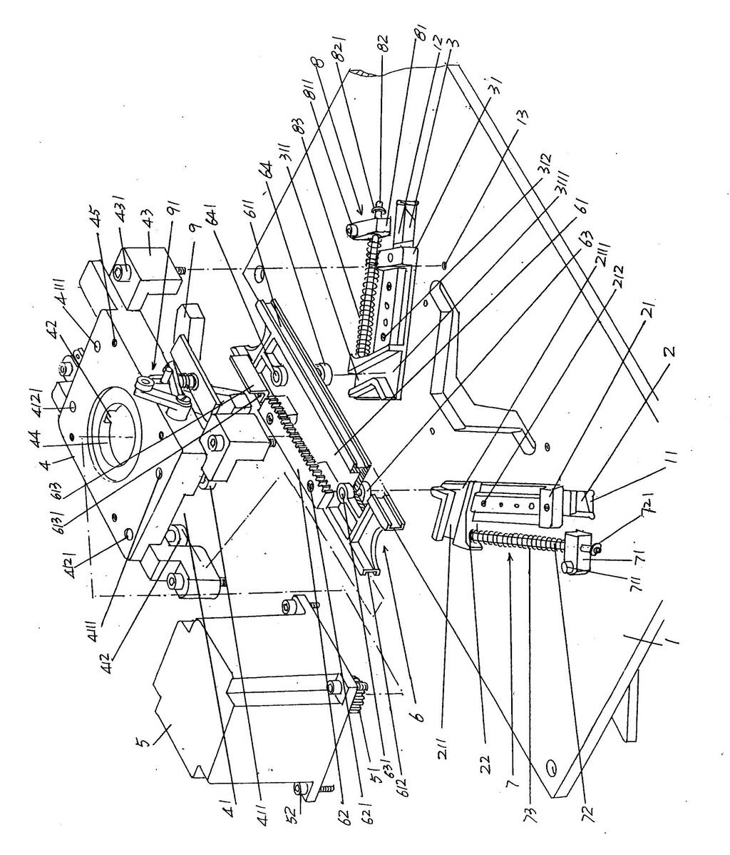
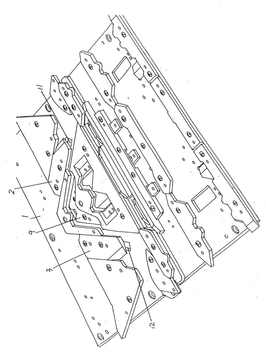
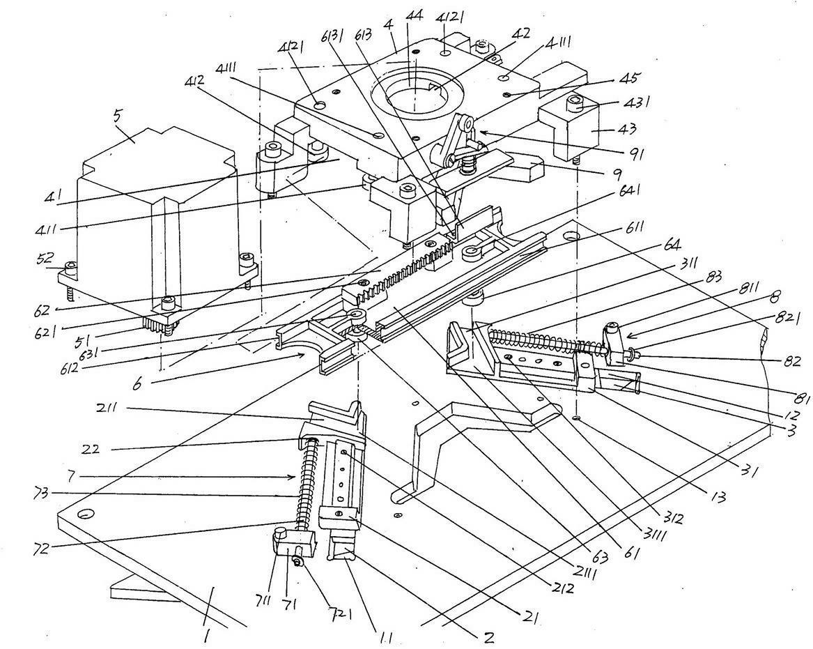
[0020] See figure 1 , according to the known technology, the triangular base plate 1 of the computerized flat knitting machine has a pair of the same structure, which is called the front triangular base plate and the rear triangular base plate in the industry. The following description is for one of the triangular base plates 1. On the triangular bottom plate 1 and at a position corresponding to the left...


PUM


Abstract

A density triangular adjusting mechanism of a computer flat knitting machine belongs to the technical field of knitting machinery. The computer flat knitting machine comprises a triangular baseboard, a left density triangle and a right density triangle, wherein the left density triangle and the right density triangle are provided with a left density triangular guiding block and a right density triangular guiding block. The density triangular adjusting mechanism comprises a base, a motor and a synchronous moving device. The density triangular adjusting mechanism is characterized in that a first guiding wheel groove is arranged at one end where the left density triangular guiding block is matched with the synchronous moving device and faces one lateral surface of the synchronous moving device, a second guiding wheel groove is arranged at one end where the right density triangular guiding block is matched with the synchronous moving device and faces one lateral surface of the synchronous moving device, a left density triangular reset device and a right density triangular reset device are arranged on the triangular baseboard, the left density triangular reset device comprises a fist spring rod base, a first spring rod and a first spring, and the right density triangular reset device comprises a second spring rod base, a second spring rod and a second spring. The density triangular adjusting mechanism has the advantages of simplifying the structure, reflecting energy-saving performance, reducing fault probability or even avoiding fault, and being favorable for reflecting economy.

Description

technical field [0001] The invention belongs to the technical field of knitting machinery, and in particular relates to a density triangle adjustment mechanism of a computerized flat knitting machine. Background technique [0002] As known in the industry, the sparse density of different braids is different, and the change of the sparse density of the braid is realized by the position change of the density triangle on the triangular bottom plate, and the position change of the density triangle is achieved through the density triangle The density triangle adjustment mechanism is usually called the density triangle control mechanism or the drive mechanism. The movement trajectory of the knitting needles on the needle bed (also known as the needle plate) is changed by adjusting the position of the density triangle by the density triangle adjustment mechanism. [0003] The aforementioned technical information of the density triangular adjustment mechanism of the computerized fl...

Claims


Application Information

Patent Timeline
Patent Type & Authority Applications(China)
IPC IPC(8): D04B15/36D04B15/96
Inventor 金永良付洪平钱新华
Owner JIANGSU JINLONG TECHNOLOGY CO LTD
Why Eureka
Try Eureka