Butanediol spraying vacuum pump and working method thereof

A technology of jet vacuum pump and butanediol, which is applied to jet pumps, pumps, non-volume pumps, etc., can solve the problems of high energy consumption, waste of manpower, material resources, and financial resources, and achieve continuous production, reduced maintenance, and extended The effect of maintenance intervals

Active Publication Date: 2012-07-04
杭州华达喷射真空设备有限公司
View PDF5 Cites 3 Cited by
  • Summary
  • Abstract
  • Description
  • Claims
  • Application Information

AI Technical Summary

Problems solved by technology

Its disadvantages: the Roots pump unit is a mechanical pump. In order not to affect the continuous production, two pumps need to be connected in parallel. In the case of long-term continuous oper

Method used


Image

  • Butanediol spraying vacuum pump and working method thereof
  • Butanediol spraying vacuum pump and working method thereof

Examples


Embodiment 1

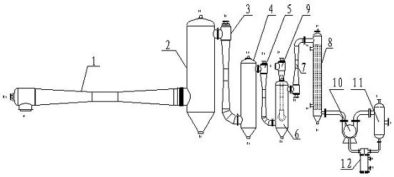
[0009] Embodiment 1: with reference to attached figure 1 . A butanediol jet vacuum pump, the first-stage butanediol ejector 1 communicates with the lower part of the first-stage condenser 2, the upper part of the first-stage condenser 2 communicates with the upper part of the second-stage butanediol ejector 3, and the second-stage butanediol ejector The lower part of 3 communicates with the lower part of the secondary condenser 4, the upper part of the secondary condenser 4 communicates with the upper part of the third-stage butanediol injector 5, the lower part of the third-stage butanediol injector 5 communicates with the lower part of the third-stage condenser 6, and the third-stage condensing The upper part of the device 6 communicates with the lower part of the four-stage butanediol injector 7, the three-stage auxiliary steam ejector 9 communicates with the upper end of the three-stage condenser 6, the upper part of the four-stage butanediol injector 7 communicates with t...

Embodiment 2

[0010] Embodiment 2: On the basis of Embodiment 1, a working method of a butanediol jet vacuum pump, when working, the butanediol gas produced in the final polycondensation reactor of engineering plastics or degradable plastic polyester production line enters the first-stage butanediol Glycol steam ejector 1, the butanediol gas from the pre-condensation reactor enters the three-stage auxiliary steam ejector 9, and the pumped gas is condensed by the first, second, and third-stage spray condensers 2, 4, and 6. The fourth-stage butanediol vapor ejector 7 is pumped into the tube condenser 8. After cooling, the non-condensable gas in the pumped gas is pumped away by the Roots liquid ring vacuum pump unit 10 and discharged to the atmosphere or the tail gas treatment system; The butanediol liquid in the liquid-sealed storage tank is pumped out by the circulation pump, and part of it is supplied to the interstage condensers 2, 4, 6 through the heat exchanger 12, and part of it is suppl...


PUM


Abstract

The invention relates to a butanediol spraying vacuum pump. The pump of the invention is characterized in that a primary butanediol sprayer is connected with a lower portion of a primary condenser, an upper portion of the primary condenser is connected with an upper portion of a secondary butanediol sprayer, a lower portion of the secondary butanediol sprayer is connected with a lower portion of a secondary condenser, an upper portion of the secondary condenser is connected with an upper portion of a third butanediol sprayer, a lower portion of the third butanediol sprayer is connected with a lower portion of a third condenser, an upper portion of the third condenser is connected with a lower portion of a fourth butanediol sprayer, a third auxiliary steam sprayer is communicated with an upper end of the third condenser, an upper portion of the fourth butanediol sprayer is communicated with an upper portion of a fourth condenser, a lower portion of the fourth condenser is connected with a vapor-liquid separator by a liquid-ring vacuum pump, one end of a heat exchanger is communicated with the liquid-ring vacuum pump and the other end of the heat exchanger is communicated with the vapor-liquid separator. The butanediol spraying vacuum pump has the advantages that: no waste liquid is discharged; the energy consumption is reduced; the steam spray vacuum pump in the invention has no moving part during runtime, the butanediol spraying vacuum pump is suitable for long-term and continuous operation, and the maintenance period is prolonged.

Description

technical field [0001] The invention relates to a jet vacuum pump, in particular to a butanediol jet vacuum pump using butanediol as a working medium and a working method thereof, belonging to the field of vacuum pump manufacture. Background technique [0002] All of the applicant’s prior patent application CN 101624980A, titled “A Butanediol Jet Vacuum Pump and Working Method”, includes three interstage condensers, the lower part of the first condenser communicates with the first stage butanediol steam ejector, The upper part communicates with the bottom of the second condenser through a two-stage butanediol steam ejector; the upper part of the second condenser communicates with the lower part of the third condenser through a three-stage butanediol steam ejector; the upper part of the third condenser passes through The pipe fittings are connected with the Roots liquid ring vacuum pump unit; the gas-liquid separator and the indirect heat exchanger are connected in series wit...

Claims


Application Information

Patent Timeline
IPC IPC(8): F04F5/54
Inventor 胡在定
Owner 杭州华达喷射真空设备有限公司
Why Eureka
Try Eureka