Connecting assembly for combining hydraulic components

A technology for connecting sleeves and hydraulic machinery, which is applied in the hydraulic field and can solve problems such as inability to insert connecting sleeves and small manufacturing tolerances

Inactive Publication Date: 2012-07-04
ABB TECH AG
View PDF4 Cites 0 Cited by
  • Summary
  • Abstract
  • Description
  • Claims
  • Application Information

AI Technical Summary

Problems solved by technology

However, the disadvantage of using such connecting sleeves is that such connecting sleeves can only connect the pipes of the elements together if the pipes of the elements are precisely aligned with each other, because otherwise the connecting sleeves would be cannot be inserted into a link section
Espe

Method used


Image

  • Connecting assembly for combining hydraulic components
  • Connecting assembly for combining hydraulic components
  • Connecting assembly for combining hydraulic components

Examples


Embodiment Construction

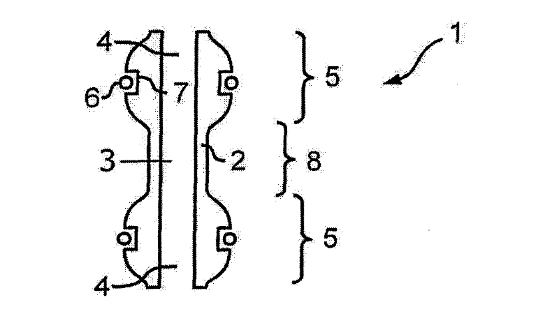
[0035] figure 1 A schematic cross-sectional view of a connecting sleeve 1 according to an embodiment of the present invention is shown in FIG. The connecting sleeve 1 has a cylindrical sleeve body 2 which encloses a cavity 3 . The sleeve body 2 is open on its front end face 4 so as to form a connection channel for conducting hydraulic fluid. The cross-section of the cavity 3 can basically be of any shape, but a connecting sleeve with a circular cross-section is usually used, enabling insertion in all directions of rotation.

[0036] In most cases, a sealing area 5 is provided at one end of the connecting sleeve 1 . In this sealing area 5, the diameter of the sleeve body 2 is thickened, so that the diameter of the sleeve body 2 on the sealing area 5 (transversely with respect to the axial direction) is larger than that of the sleeve remote from the corresponding end section The diameter of the sleeve body 2 in the intermediate region 8 of the tube body 2 . According to actu...


PUM


Abstract

The invention relates to a connecting sleeve (1) for combining pipelines (13,14). The sleeve (1) has a hollow cylinder-shaped sleeve body (2) whose end is provided with a spherical or segment-like structured connecting area (5) as a thickening part. An elastic rounding seal element (6) is arranged on the axial position of the maximum cross section in the connecting area (5).

Description

technical field [0001] The present invention relates primarily to the field of hydraulics, in particular to the connection of elements with hydraulic conduits, and in particular to connection techniques for the pressure-tight connection of conduits of elements, such as these elements on hydro-mechanical power switch drives in gas-insulated high-voltage switchgear Applications. Background technique [0002] Typically, hydraulic elements have conduits for conducting hydraulic fluid, such hydraulic elements being interconnected by means of one or more seals. These seals can be used to prevent the escape of hydraulic fluid in the pipeline even under high pressure. [0003] A solution for connecting elements consists in providing a radially sealing O-ring in a groove on at least one element surrounding the conduit opening. When the elements are stacked on top of each other, the nozzles of the pipes cover each other. The O-ring arranged in the groove then bears against the surf...

Claims


Application Information

Patent Timeline
IPC IPC(8): F16L27/113
CPCF16L27/023F16L27/113F16L27/1017H01H33/34F15B19/00F16L21/02F16L25/00
Inventor 马蒂亚斯·施密特
Owner ABB TECH AG
Why Eureka
Try Eureka