Heat supply equipment

The technology of heating equipment and mixer is applied in the field of heating equipment for high-temperature hot water, which can solve the problems of increased power consumption, loss of thermal energy and pressure of thermal stations, and consumption of human resources.

Inactive Publication Date: 2012-07-04
SHANGHAI PANDA MACHINEGRP CO LTD
View PDF4 Cites 9 Cited by
  • Summary
  • Abstract
  • Description
  • Claims
  • Application Information

AI Technical Summary

Problems solved by technology

Since the plate heat exchanger will generate a certain resistance (about 0.10MPa), this will lead to an increase in the load of the heating booster pump and an increase in power consumption during work. At the same time, because the heat exchange efficiency of the plate heat exchanger cannot reach 100 %, so the heat energy and pressure provided by the thermal station will be lost in vain, and the heating cost will be increased. The installation of the plate heat exchanger is complicated, and it also needs regular cleaning and maintenance, which consumes a lot of human resources

Method used


Image

  • Heat supply equipment
  • Heat supply equipment

Examples


Embodiment Construction

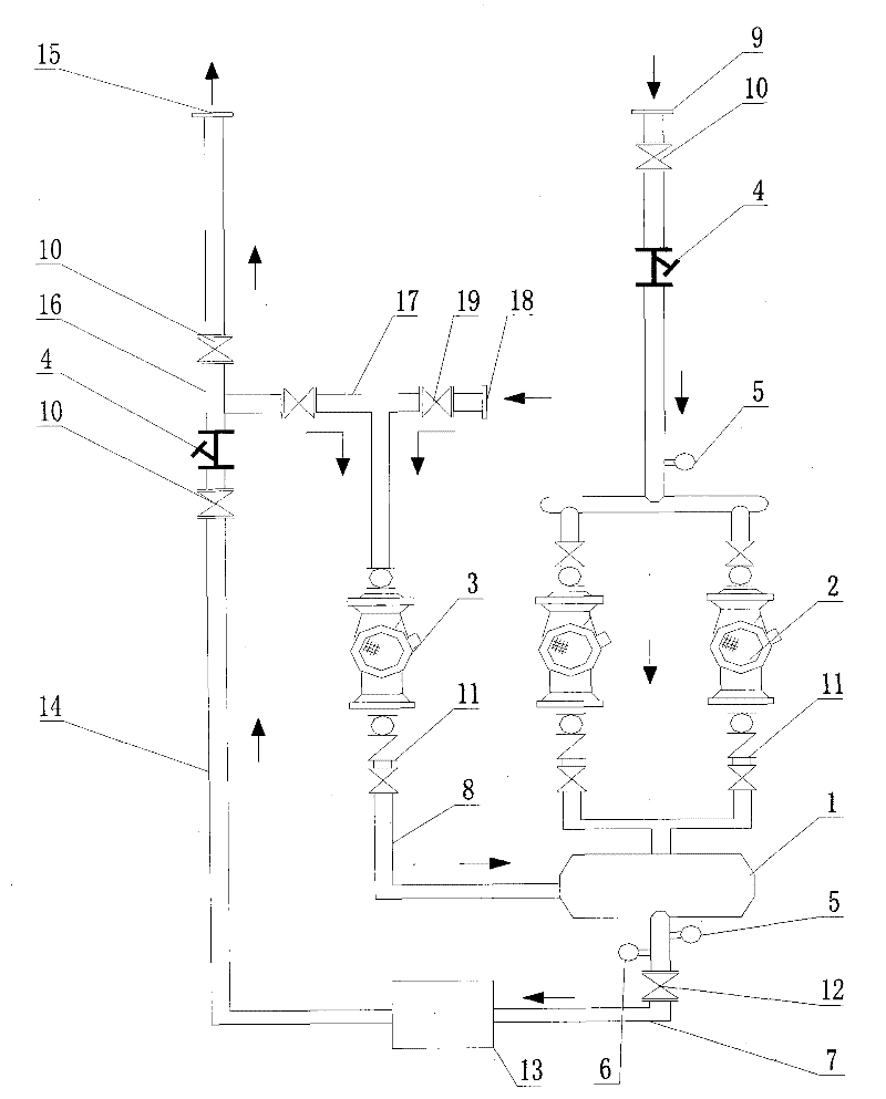
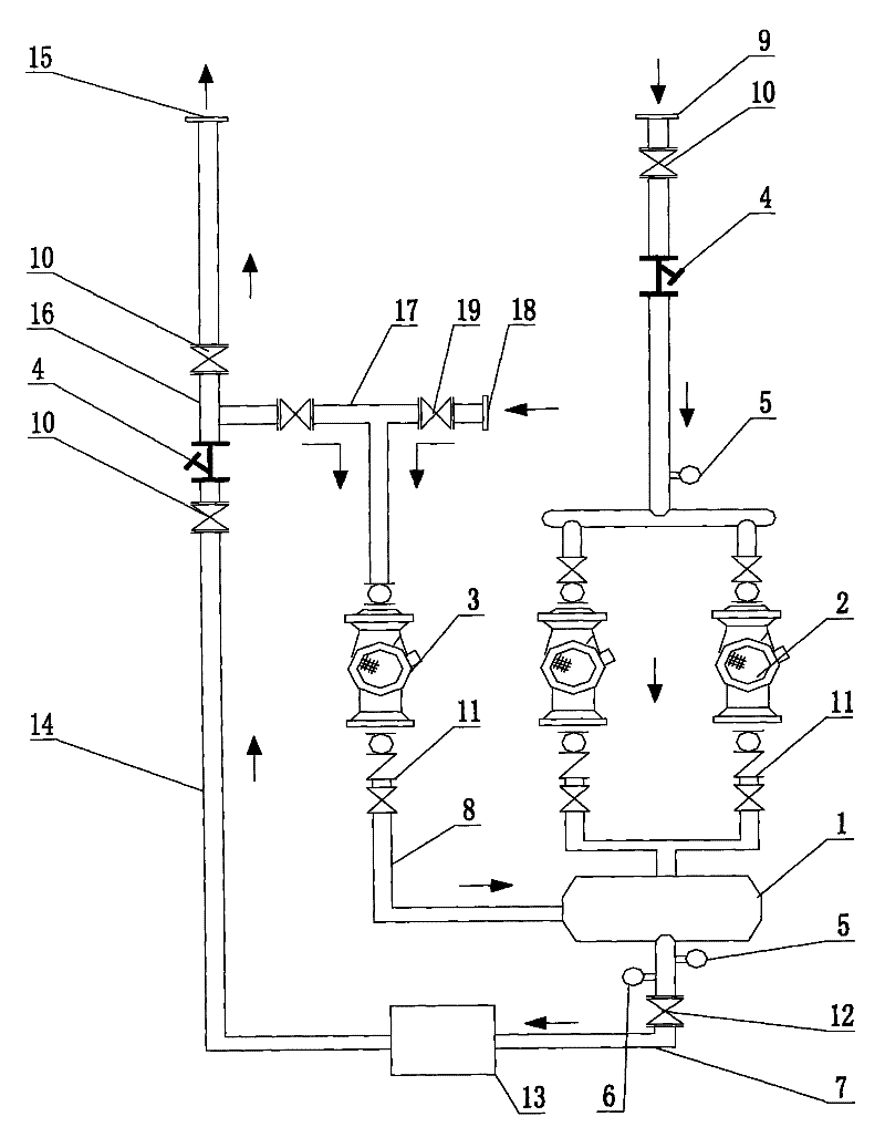
[0007] like figure 1 The shown heating equipment is composed of a mixer 1, a circulating pump 2, a temperature regulating pump 3, a filter 4, a pressure sensor 5, a temperature sensor 6, connecting pipes and the like. The high-temperature water source of the thermal station is connected to the inlet of the circulation pump 2 through the nozzle 9, the valve 10, and the filter 4. The outlet of the circulation pump 2 is connected to the mixer 1 after passing through the valve group 11, and the outlet of the mixer 1 is connected to the valve 12. The connecting pipe 7 is connected with the heat load 13 for the user, so that heat can be supplied to the heat load for the user. The low-temperature return water of the heat load 13 for the user passes through the return pipe 14. A valve 10 and a filter 4 are installed, and a There is a nozzle 15 connected to the recovery pipe network of the heat station, the return pipe 14 is connected to the water inlet of the temperature regulating pu...


PUM


Abstract

The invention discloses heat supply equipment which consists of a mixer, a valve, a sensor, a circular pump, a temperature regulating pump, a filter, a connecting tube and a control system, wherein a water inlet of the circular pump passes through the filter and the valve and then is directly connected with a high-temperature water source pipe mouth of a heating station; a water pump outlet passes through a valve blank and then is connected with the mixer; a mixer outlet passes through the valve and then is connected with the heat equipment; an outlet of the temperature regulating pump passes through the valve blank and then is connected with the mixer; an inlet of the temperature regulating pump is connected with a water supplementing port through one end of a tee joint; the other end of the temperature regulating pump is connected with a low-temperature water return pipe; and the low-temperature water return pipe is respectively connected with the heat equipment and a reclaimed water pipe mouth of the heating station through the tee joint. Due to the adoption of the structure, high-temperature incoming water of the heating station is pressurized into the mixer by the circular pump; meanwhile, low-temperature water in water reclaimed by a user or normal temperature softened water used for the first time is pumped into the mixer by the temperature regulating pump; and the mixer is used for mixing two kinds of water with different temperatures, and then conveying the water to the inside of the heat equipment of the user after the temperature of water is reduced to the temperature of the water required by the user, to form a heat supply system.

Description

1: Technical field [0001] The invention relates to a heating device used in a heating system, in particular to a heating device whose heat source is high-temperature hot water. Two: background technology [0002] The heat supply system in the prior art is not suitable for direct delivery to the user for heat supply because the temperature of the heat source water provided by the thermal station is very high (generally can reach more than 100 degrees, and the temperature required by the user is about 80 degrees). Generally, it is necessary to use heat exchange equipment for heat supply. At present, heat exchangers (plate heat exchange units) are generally used in China to convert the temperature of the heat source and reduce the temperature for heat supply. Since the plate heat exchanger will generate a certain resistance (about 0.10MPa), this will lead to an increase in the load of the heating booster pump and an increase in power consumption during work. At the same time, b...

Claims


Application Information

Patent Timeline
Patent Type & Authority Applications(China)
IPC IPC(8): F24D19/00F24D19/10
Inventor 池学聪谭红全
Owner SHANGHAI PANDA MACHINEGRP CO LTD
Why Eureka
Try Eureka