Novel natural gas liquefaction system and natural gas liquefaction method

A liquefaction system and natural gas technology, applied in the field of gas liquefaction, to achieve the effect of high liquefaction rate

Inactive Publication Date: 2014-08-06
XI AN JIAOTONG UNIV +1
View PDF9 Cites 2 Cited by
  • Summary
  • Abstract
  • Description
  • Claims
  • Application Information

AI Technical Summary

Problems solved by technology

However, the above three processes are not suitable for direct application in urban natural gas gate stations, and the development of natural gas liquefaction process for peak-shaving facilities in urban gate stations is particularly important

Method used


Image

  • Novel natural gas liquefaction system and natural gas liquefaction method
  • Novel natural gas liquefaction system and natural gas liquefaction method
  • Novel natural gas liquefaction system and natural gas liquefaction method

Examples


Embodiment 1

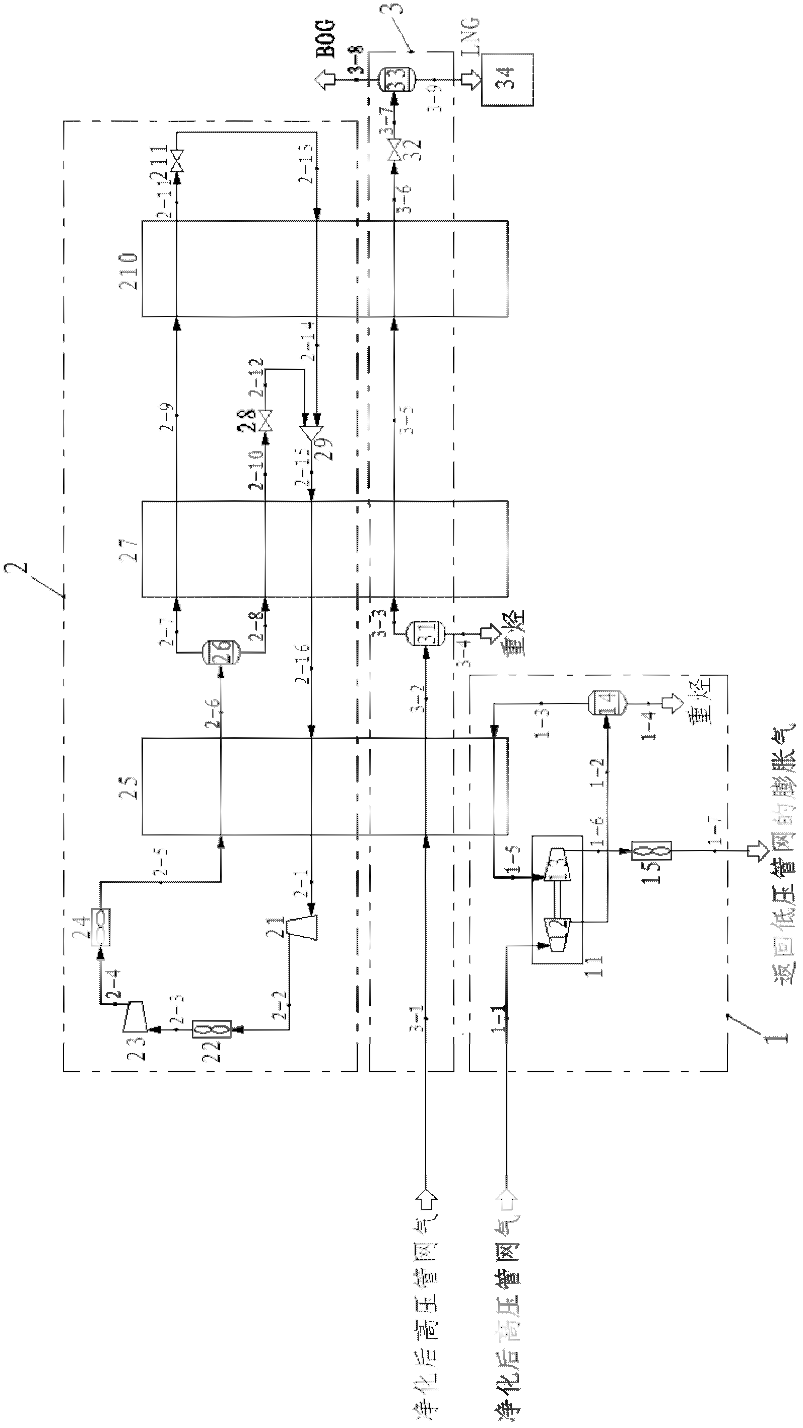
[0048] Such as figure 1 As shown, the natural gas liquefaction process of the present invention includes an expansion precooling system 1 , a mixed refrigerant circulation system 2 and a natural gas liquefaction circuit 3 .

[0049] Expansion pre-cooling system 1, a part of natural gas from the high-pressure pipe network, the pressure and temperature are 3.7MPa and 308.15K respectively, enter the expansion end 12 of the expander 11 for expansion, the pressure drops to about 0.55MPa, the temperature drops to about 221K, and then passes through Expansion gas-liquid separator 14 removes heavy hydrocarbons and other high-boiling point components to condensate, and part of the gas phase flows into the fourth channel of pre-cooling heat exchanger 25 to provide cooling capacity for pre-cooling heat exchanger 25. After sufficient heat exchange The temperature rises to about 290K, then flows into the booster end 13 of the expander 11, pressurizes to about 1.18MPa, the temperature rises...

Embodiment 2

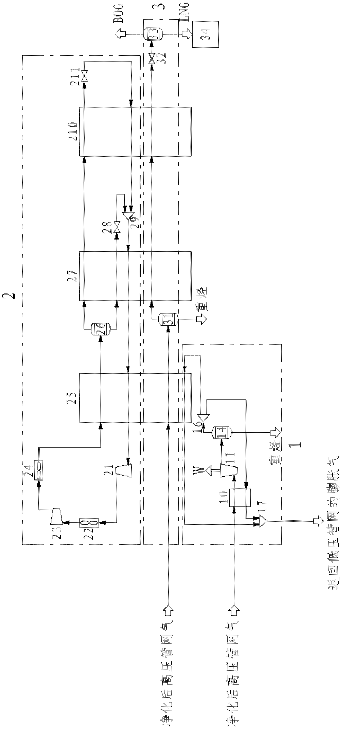
[0054] figure 2 is a schematic diagram of Embodiment 2 of the present invention, which is similar to figure 1 Said embodiment 1, figure 2 The process shown is the same as figure 1 The differences in the flow shown are: (1), figure 2The expansion gas from the high-pressure pipe network enters the expander 11 for expansion and first enters the expansion gas regenerator 10 for cooling, and the cooling capacity of the expansion gas regenerator 10 is provided by a part of the expanded expansion gas; (2), the expander 11 No pressurization end is set, the expansion gas is directly expanded to the pressure of the low-pressure pipe network in the expander 11, and the resulting expansion work can be recovered for power generation or used for other purposes; (3), installed after the expansion gas-liquid separator 14 The expanded gas separator 16 is used to adjust the ratio of the two streams flowing into the pre-cooling heat exchanger 25 and the returned expanded gas recuperator 10...

Embodiment 3

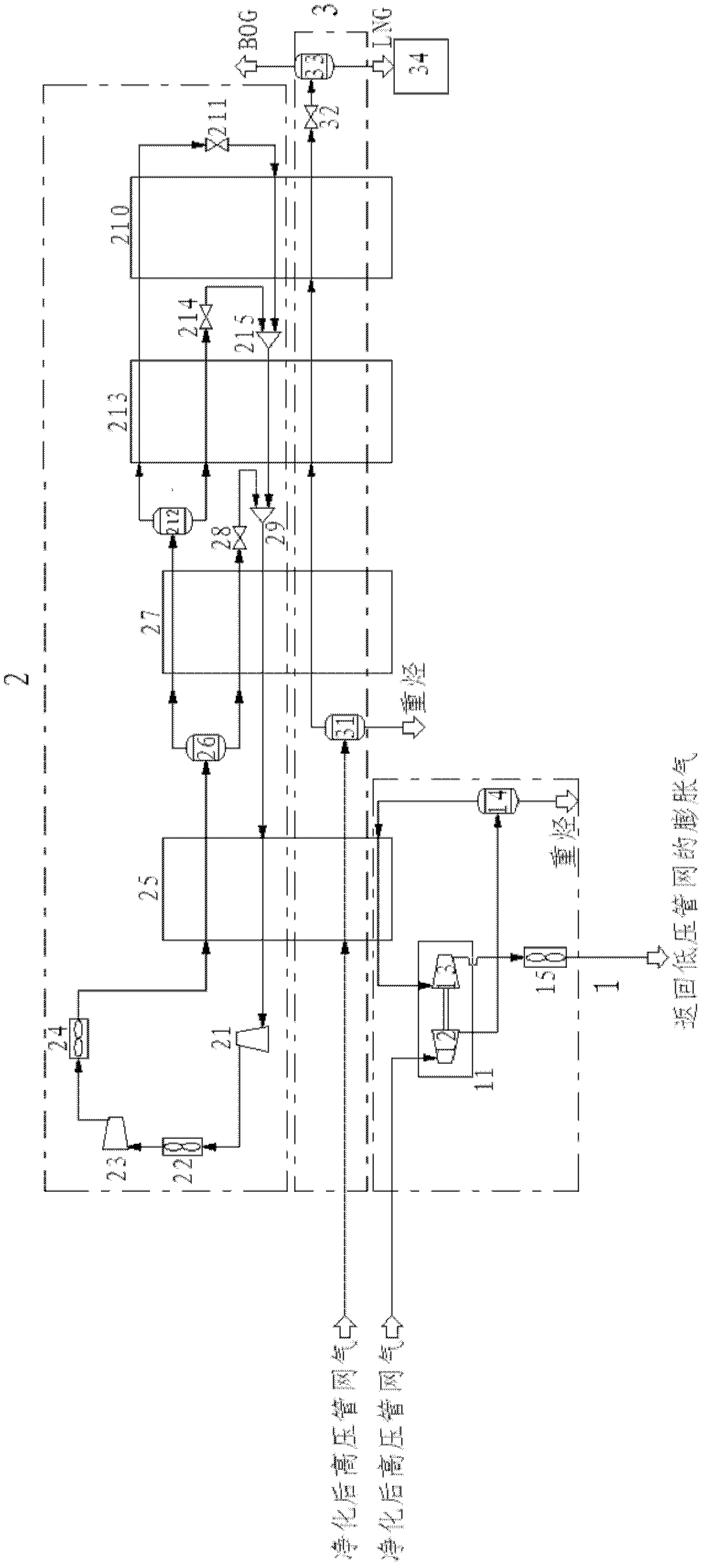
[0056] image 3 is a schematic diagram of embodiment 3 of the present invention, which is similar to figure 1 Said embodiment 1, image 3 The process shown is the same as figure 1 The differences in the flow shown are: (1), image 3 In front of the subcooling heat exchanger 210, a primary heat exchanger is added, which is called the second main heat exchanger 213, forming a precooling heat exchanger 25, two-stage main heat exchangers (27, 213) and supercooling The four-stage heat exchanger mixed refrigeration cycle of the cold heat exchanger 210; (2), the newly added second main heat exchanger 213 and its auxiliary equipment are basically the same as the first main heat exchanger 27, and the second main heat exchanger 213 A second mixed refrigerant gas-liquid separator 212 is arranged at the front end to separate the two-phase refrigerant flowing out of the first flow channel of the first main heat exchanger 27; a third throttling device is arranged at the rear end of the s...


PUM


Abstract

The invention discloses a novel natural gas liquefaction system and a natural gas liquefaction method. The natural gas liquefaction system comprises an expansion precooling system, a mixed refrigerant circulating system and a natural gas liquefaction loop. Refrigeration of an expander is combined with mixed refrigerant circulating refrigeration, the expansion precooling system provides energy for precooling natural gas and mixed refrigerant, and the mixed refrigerant circulating refrigeration provides cold energy for liquefying the natural gas. The liquefaction system and the natural gas liquefaction method make full use of pressure energy among high-low pressure pipe networks of urban natural gas stations, and are high in efficiency, energy-saving and high in liquefaction ratio.

Description

【Technical field】 [0001] The invention relates to the technical field of gas liquefaction, in particular to a natural gas liquefaction system and a method thereof. 【Background technique】 [0002] As a high-quality clean energy, natural gas is mainly composed of methane, and also includes a small amount of alkane gases such as ethane and propane, as well as other gases such as water, nitrogen and carbon dioxide. After natural gas is liquefied, its volume is reduced to about 1 / 625 of its original volume, so LNG (Liquefied Natural Gas) is easier to store and transport than natural gas. In addition, LNG is safer and more environmentally friendly, and it is of great significance in urban gas peak shaving and valley filling. [0003] Currently common natural gas liquefaction processes include cascade refrigeration cycle, mixed refrigerant cycle and expansion refrigeration cycle. The cascade cycle is mainly used in large-scale base-load liquefaction units. Its advantages are low ...

Claims


Application Information

Patent Timeline
Patent Type & Authority Patents(China)
IPC IPC(8): F25J1/02
CPCF25J1/0022F25J1/0037F25J1/0055F25J1/0212F25J1/0232F25J1/0265F25J2210/06F25J2220/62F25J2220/64F25J2230/20F25J2230/32
Inventor 吴江涛李清张雷李持佳毕胜山常旭宁孟现阳李翠超
Owner XI AN JIAOTONG UNIV
Why Eureka
Try Eureka