Automatic ageing and testing device and method

A test device and automatic technology, applied in the direction of measuring devices, measuring electricity, measuring electrical variables, etc., can solve the problems of limited production capacity, no enterprise, low efficiency, etc., achieve stable product quality, high degree of automation, and improve production efficiency.

Active Publication Date: 2012-07-04
DONGGUAN GUANJIA ELECTRONICS EQUIP
View PDF4 Cites 16 Cited by
  • Summary
  • Abstract
  • Description
  • Claims
  • Application Information

AI Technical Summary

Problems solved by technology

Obviously, in this kind of production process, all aging and testing stations are manually operated, which takes up a lot of human resources, and there are potential safety hazards for personnel to suffer from work-related injuries. Moreover, products are placed and placed many times at aging and testing stations, which limits the expansion of production capacity. Improvement, not only low efficiency but also unstable product quality, unable to meet the needs of mass product testing
[0003] In order to solve the above technical problems and improve production efficiency, the Chinese invention patent (patent number: 201020604668.4) discloses a mobile automatic aging line for power supply parts. Line device, aging device and control device. Although this process realizes the automation of the aging test process, simplifies the aging process, does not require manual handling and manual timing operation procedures, and improves production efficiency, but its defects are: 1) the above-mentioned automatic The aging line only realizes the automatic control of the aging process of electronic products. After the aging of electronic products, various performances must be tested to ensure whether the quality meets the requirements. Obviously, after the electronic products come out of the automatic aging line, there is still It is necessary to manually connect the electronic product to the test equipment to complete the test process
At present, there is no domestic enterprise capable of producing such automated assembly line equipment.

Method used


Image

  • Automatic ageing and testing device and method
  • Automatic ageing and testing device and method
  • Automatic ageing and testing device and method

Examples


Embodiment 1

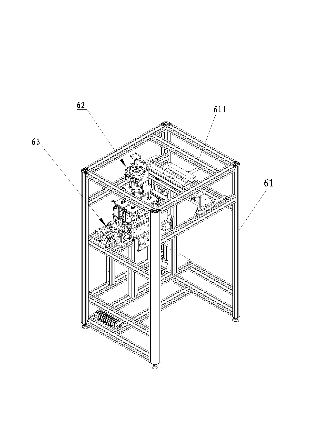
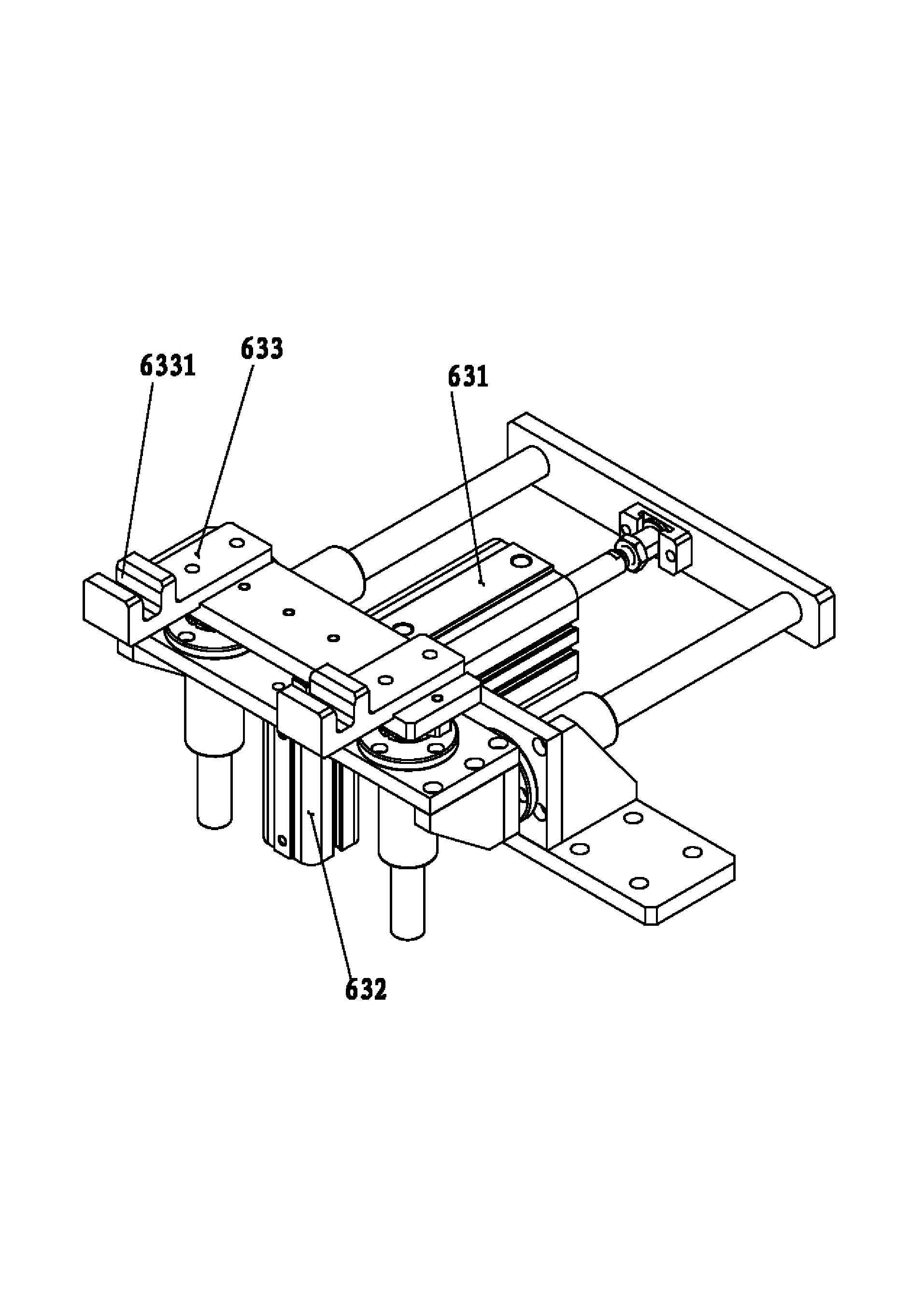
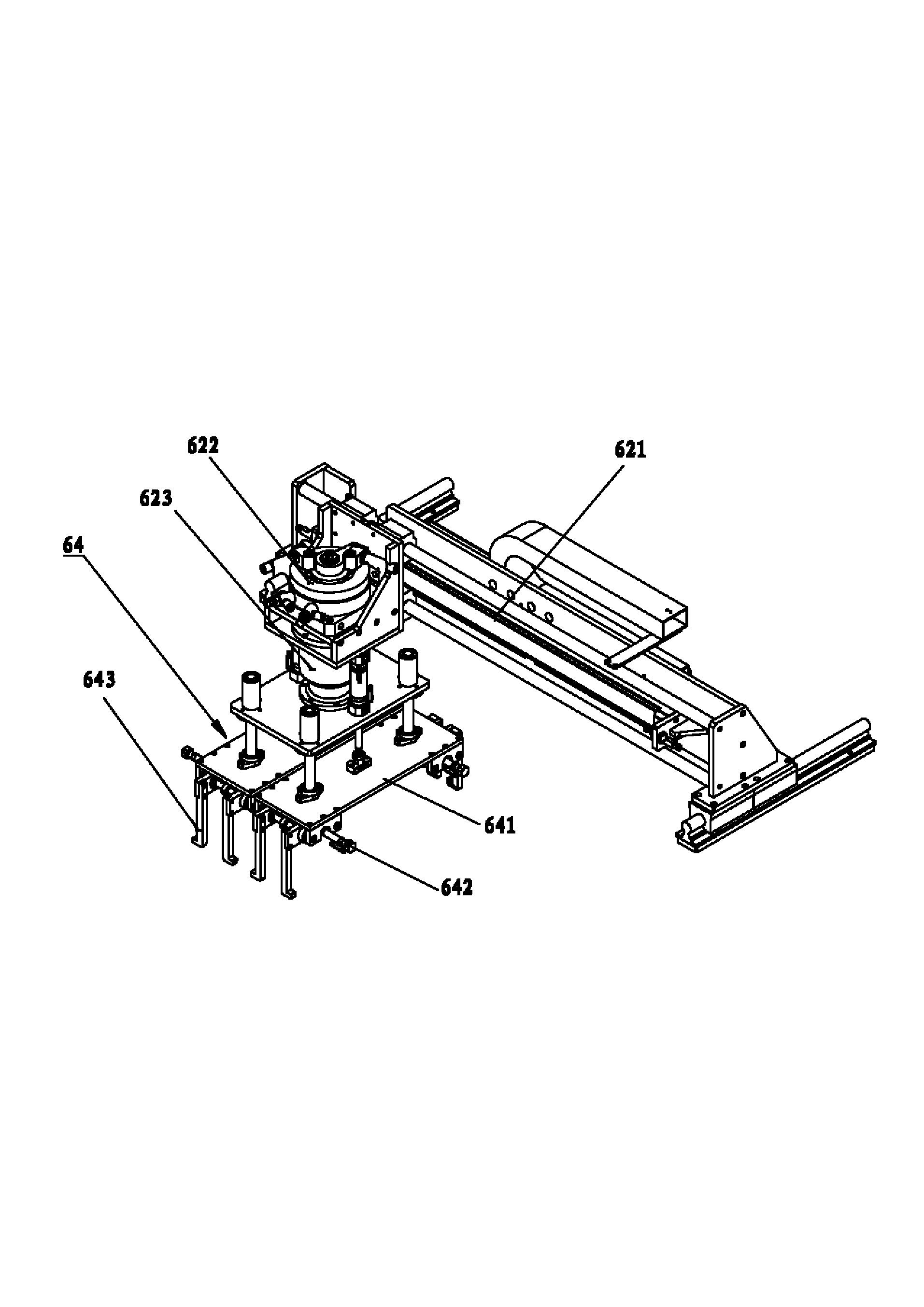
[0069] Embodiment 1 of an automatic aging and testing device of the present invention is as Figure 1 to Figure 12 As shown, it includes a frame 1, a child fixture 2 and a mother fixture 4 that can be used in conjunction with each other, an aging mechanism 3 and a testing mechanism 5 that are respectively arranged on the frame 1, and separate the child fixture 2 and the mother fixture 4. The separating mechanism 6 and the control device capable of controlling the separating mechanism 6 , the aging mechanism 3 and the testing mechanism 5 .

[0070] When working, the electronic product 10 is loaded into the sub-fixture 2 at the upper machine position, and then the sub-fixture 2 and the mother jig 4 are combined at the sub-mother jig assembly station and then transported to the aging mechanism 3 for automatic aging. After the completion, the child fixture 2 and the mother fixture 4 are transported to the separation mechanism 6, and the separation mechanism 6 separates the child f...

Embodiment 2

[0081] A kind of automatic aging and testing device of this embodiment can be found in Figure 5 to Figure 9 , on the basis of Embodiment 1, the features not explained in this embodiment adopt the explanations in Embodiment 1, and will not be repeated here. The difference between this embodiment and embodiment 1 is:

[0082] refer to Figure 6 and Figure 7 , the sub-fixture 2 includes a base 21 and an upper cover 22 arranged above the base 21, the base 21 is provided with a base PCB, the base PCB is provided with a sub-fixture DC signal connection device 211, the base 21 is opposite to the upper cover 22 A product placement slot 213 is provided on the inner surface for placing the electronic product 10, and a DC signal interface 212 is provided in the product placement slot 213, and the DC signal interface 212 is electrically connected to the DC signal connection device 211 of the sub-fixture through the base PCB board;

[0083] refer to Figure 8 , the upper cover 22 is ...

Embodiment 3

[0094] A kind of automatic aging and testing device of this embodiment can be found in Figure 10 and Figure 11 , on the basis of Embodiment 1, the features not explained in this embodiment adopt the explanations in Embodiment 1, and will not be repeated here. The difference between this embodiment and embodiment 1 is:

[0095] refer to Figure 10 , the automatic aging and testing device also includes a translation mechanism 7 for transporting the child fixture 2 and the mother fixture 4 to the aging mechanism 3 or the testing mechanism 5, the translation mechanism 7 includes a burn-in terminal and a test terminal, and the burn-in terminal and the burn-in mechanism 3 is connected to the input end, and the test end is connected to the input end of the test mechanism 5, so as to realize the transition between the aging process and the test process of the child fixture 2 and the mother fixture 4.

[0096] refer to Figure 11 The translation mechanism 7 includes a translation...


PUM


Abstract

The invention relates to the technical field of ageing testing, in particular to an automatic ageing and testing device and an automatic ageing and testing method. The device comprises a frame, a son jig and a mother jig which are matched, an ageing mechanism and a testing mechanism which are arranged on the frame, a separation mechanism for separating the son jig and the mother jig, and a control device which can control the separation mechanism, the ageing mechanism and the testing mechanism, wherein the separation mechanism comprises a separator frame, a separating mechanical arm arranged on the separator frame in a sliding way, and a disengaging mechanism which can separate the son jig from the mother jig. Compared with the prior art, the automatic ageing and testing device and the automatic ageing and testing method automatically age and test electronic products on a production line, and have the advantages of high production efficiency, and stable product quality.

Description

technical field [0001] The invention relates to the technical field of aging testing, in particular to an automatic aging and testing device and a method thereof. Background technique [0002] With the development of society, people have higher and higher requirements for the quality of electronic products. In order to improve the quality of electronic products, it is necessary to carry out aging tests on electronic products before leaving the factory. In the prior art, when carrying out burn-in tests on electronic products, the production process of belt transmission is generally adopted. All the burn-in and test links are manually operated. First, the operators put the products on the burn-in fixture one by one, and then the burn-in Fixtures are placed in the aging room for aging. After the aging is completed, the test equipment is connected one by one for various performance tests. After the test is completed, the products are put back on the belt one by one and transport...

Claims


Application Information

Patent Timeline
Patent Type & Authority Applications(China)
IPC IPC(8): G01R31/01G01R1/02B25J9/08
Inventor 李垂猛刘坚辉邵继铭
Owner DONGGUAN GUANJIA ELECTRONICS EQUIP
Why Eureka
Try Eureka