
Digital flash lamp and method for controlling flashing of digital flash lamp

A flash, digital technology, applied in the field of intelligent monitoring, can solve the problems of long charging time, unstable trigger time, slow flash charging speed, etc., to achieve uniform flash energy output, accurate and controllable trigger flash time, and improve charging efficiency.

Active Publication Date: 2014-06-18
北京数字智通科技有限公司
View PDF4 Cites 0 Cited by
  • Summary
  • Abstract
  • Description
  • Claims
  • Application Information

AI Technical Summary

Problems solved by technology

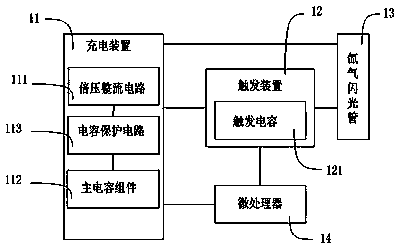
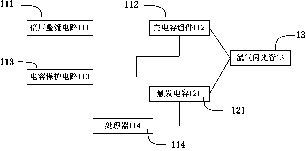
[0004] In order to solve the problems of slow charging speed, long charging time and unstable triggering time of the flashlight in the prior art, the present invention provides a digital flashlight, including a charging device, a triggering device, a xenon flash tube and a microprocessor, wherein the The microprocessor controls the charging device to charge the xenon flash tube, and controls the trigger device to trigger the xenon flash tube; the charging device is connected to the trigger device to charge it to reach a predetermined voltage; The charging device includes a voltage doubler rectifier circuit, a main capacitor component and a capacitor protection circuit, the voltage doubler rectifier circuit converts the AC voltage into a first DC voltage, and charges the main capacitor component through the capacitor protection circuit, so that The voltage of the main capacitor component is a second voltage; the trigger device includes a trigger capacitor, and the voltage across the trigger capacitor is a third voltage; the first voltage is greater than the second voltage, and the second voltage is greater than the third voltage

Method used


Image

  • Digital flash lamp and method for controlling flashing of digital flash lamp
  • Digital flash lamp and method for controlling flashing of digital flash lamp
  • Digital flash lamp and method for controlling flashing of digital flash lamp

Examples


no. 1 example

[0061] First Embodiment: Digital Flash

[0062] The present invention first proposes the first embodiment, which is a digital flashlight, please refer to figure 1 . The digital flashlight includes: a charging device 11, a triggering device 12, a xenon flash tube 13 containing xenon gas inside, and a microprocessor 14, wherein the microprocessor 14 controls the charging device 11 to charge and controls the triggering The device 12 triggers the xenon flash tube; the charging device 11 is connected to the trigger device 12 to charge it to reach a predetermined voltage.

[0063] The charging device 11 includes a voltage doubler rectifier circuit 111 , a main capacitor assembly 112 and a capacitor protection circuit 113 . The trigger device 12 includes a trigger capacitor 121 . The voltage doubler rectifier circuit 111 converts the AC voltage into a first voltage that is greater than the AC voltage and is a direct current, and the capacitor protection circuit 113 charges the m...


PUM


Abstract

The invention belongs to the field of intelligent monitoring and discloses a digital flash lamp which comprises a charging device, a trigger device, a xenon flash tube and a microprocessor. The microprocessor is used for controlling the charging device to charge the xenon flash tube and controlling the trigger device to trigger the xenon flash tube, the charging device is connected with the trigger device to charge the trigger device to reach preset voltage, and the charging device comprises a voltage doubling rectifying circuit, a main capacity assembly and a capacity protection circuit. The voltage doubling rectifying circuit can convert alternating voltage into first direct-current voltage, and the capacity protection circuit can charge the main capacity assembly to enable voltage of the main capacity assembly to be second voltage. The trigger device comprises a trigger capacitor, voltage at two ends of the trigger capacitor serves as third voltage, the first voltage is larger than the second voltage, and the second voltage is larger than the third voltage. The digital flash lamp greatly improves charging voltage, further improves charging efficiency and can achieve the effect of quick charging.

Description

technical field [0001] The invention belongs to the field of intelligent monitoring, and relates to a photographing device in intelligent transportation, more specifically, to a digital flashlight. Background technique [0002] At present, most Xenon Photoflash lamps (Xenon Photoflash) are composed of a main capacitor that stores enough energy, a trigger capacitor and a trigger coil. When triggered, the discharge of the trigger capacitor forms a high voltage on the secondary side of the trigger coil, which breaks down the inert gas in the lamp tube, and then the main capacitor releases its energy to the lamp tube. This energy will excite xenon gas in the lamp tube to generate a light source. Since the energy required to trigger the flash is provided by the storage of the main capacitor, the flash can only be triggered when the voltage of the main capacitor reaches a certain value. The speed is slow, and the charging time and triggering time are also unstable. [0003] Ther...

Claims


Application Information

Patent Timeline
Patent Type & Authority Patents(China)
IPC IPC(8): G03B15/05H05B41/36
Inventor 丁雷秦绪彬晏峰
Owner 北京数字智通科技有限公司
Learn More