Device and method for installing and adjusting reference grating of lithography equipment

A technology for reference gratings and lithography equipment, applied in the field of integrated circuit manufacturing equipment manufacturing, can solve problems such as increasing alignment errors, and achieve the effect of reducing assembly and adjustment errors

Active Publication Date: 2012-07-04
SHANGHAI MICRO ELECTRONICS EQUIP (GRP) CO LTD
View PDF4 Cites 2 Cited by
  • Summary
  • Abstract
  • Description
  • Claims
  • Application Information

AI Technical Summary

Problems solved by technology

Therefore, in the prior art, the installation and adjustment device of the reference grating will produce an actual error, and because of the existence of this error, the total alignment error will increase

Method used


Image

  • Device and method for installing and adjusting reference grating of lithography equipment
  • Device and method for installing and adjusting reference grating of lithography equipment
  • Device and method for installing and adjusting reference grating of lithography equipment

Examples


Embodiment Construction

[0047] Specific embodiments of the present invention will be described in detail below in conjunction with the accompanying drawings.

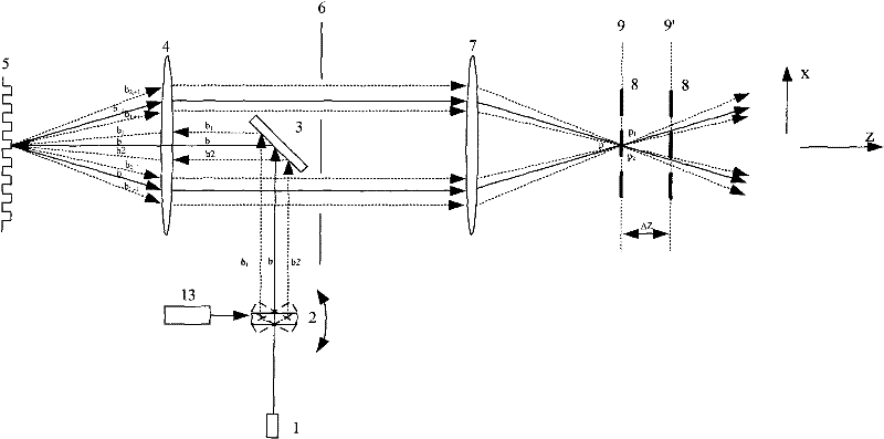
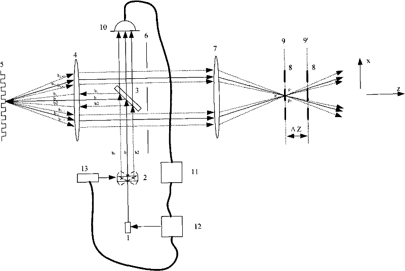
[0048] In order to overcome the technical problem in the prior art that the focal plane position found in the actual focusing process and the actual focal plane position have a deviation, a light intensity correction device is added to the grating assembly and adjustment device. The light intensity calibration device is used to adjust the output light intensity of the laser light source, to ensure that the light intensity transmitted through the vibrating mirror remains constant, and to reduce the adjustment error of the reference grating caused by the change of the projected light intensity caused by the vibrating mirror swing.

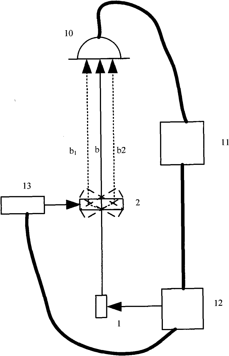
[0049] as attached figure 2 shown in the attached figure 2 It is a structural schematic diagram of the light intensity correction device disclosed in the present invention. The light intensity calibration device in...


PUM


Abstract

The invention discloses a device and a method for installing and adjusting reference grating of lithography equipment. The device sequentially comprises a laser source, a vibrating mirror, a reflecting mirror, a first lens group, a diaphragm and second lens group according to the light beam propagation direction, which are used for adjusting the reference grating to the focal plane, and the device further comprises a light intensity adjusting and calibrating unit which is used for adjusting the intensity of the light beam outputted by the laser source..

Description

technical field [0001] The invention relates to the field of integrated circuit manufacturing equipment, in particular to a device and method for setting and adjusting reference gratings in semiconductor lithography equipment. Background technique [0002] Lithography equipment is one of the important equipment for the production of large-scale integrated circuits. Photolithography equipment can transfer the pattern on the mask plate to the substrate in a certain proportion through its projection objective lens, where the substrate generally refers to all exposure objects, including substrates, coatings and photoresists. Since it is generally necessary to expose multiple layers of graphics on the device area on the substrate to finally form a specific device, it is necessary to ensure precise alignment between different layers of graphics, which is what we often call overlaying between different graphics. Accuracy is one of the three important indicators of lithography equi...

Claims


Application Information

Patent Timeline
Patent Type & Authority Applications(China)
IPC IPC(8): G03F7/20
Inventor 陈振飞王海江
Owner SHANGHAI MICRO ELECTRONICS EQUIP (GRP) CO LTD
Why Eureka
Try Eureka