
Electronic device, method of manufacturing electronic device, electronic apparatus, and moving object

a manufacturing method and electronic technology, applied in the direction of oscillator generators, electrical apparatus, pulse automatic control, etc., can solve the problems of deteriorating temperature compensation accuracy, high error, and difficulty in high accuracy adjustment, and achieve high accuracy and high reliability

Active Publication Date: 2017-03-02
SEIKO EPSON CORP
View PDF3 Cites 2 Cited by
  • Summary
  • Abstract
  • Description
  • Claims
  • Application Information

AI Technical Summary

Benefits of technology

The invention provides an electronic device that can operate with high accuracy by reducing adjustment errors caused by noise from the substrate. The device has a first digital signal and a second digital signal that are difficult to be affected by noise. The device can be accurately adjusted based on the first and second digital signals, resulting in a high-accuracy electronic device. The invention also provides a method of manufacturing the electronic device and an electronic apparatus and moving object using the high-accuracy electronic device.

Problems solved by technology

As a result, since an influence of the disturbance noise is included in the control voltage data of the variable capacitance element obtained based on the output signal of the temperature sensor, there is a possibility that the error increases to deteriorate the temperature compensation accuracy.
In particular, in the case of adjusting each of the oscillators in the state in which a number of oscillators operate at the same time such as the case of mass-producing the oscillators, since the influence of the disturbance noise is significant, it is extremely difficult to perform the adjustment with high accuracy.
According to this electronic device related to the present application example, it is possible to generate the first digital signal and the second digital signal difficult to be deteriorated in accuracy by noise due to the analog-to-digital conversion section.
According to the method of manufacturing an electronic device related to this application example, even in the environment in which the noise is easily generated due to the operation of the plurality of electronic devices, it is possible to measure the first digital signal and the second digital signal difficult to be deteriorated in accuracy by noise, and accurately adjust the operation condition of the electronic device based on the measurement result.

Method used


Image

  • Electronic device, method of manufacturing electronic device, electronic apparatus, and moving object
  • Electronic device, method of manufacturing electronic device, electronic apparatus, and moving object
  • Electronic device, method of manufacturing electronic device, electronic apparatus, and moving object

Examples


first embodiment

1-1. First Embodiment

Configuration of Oscillator

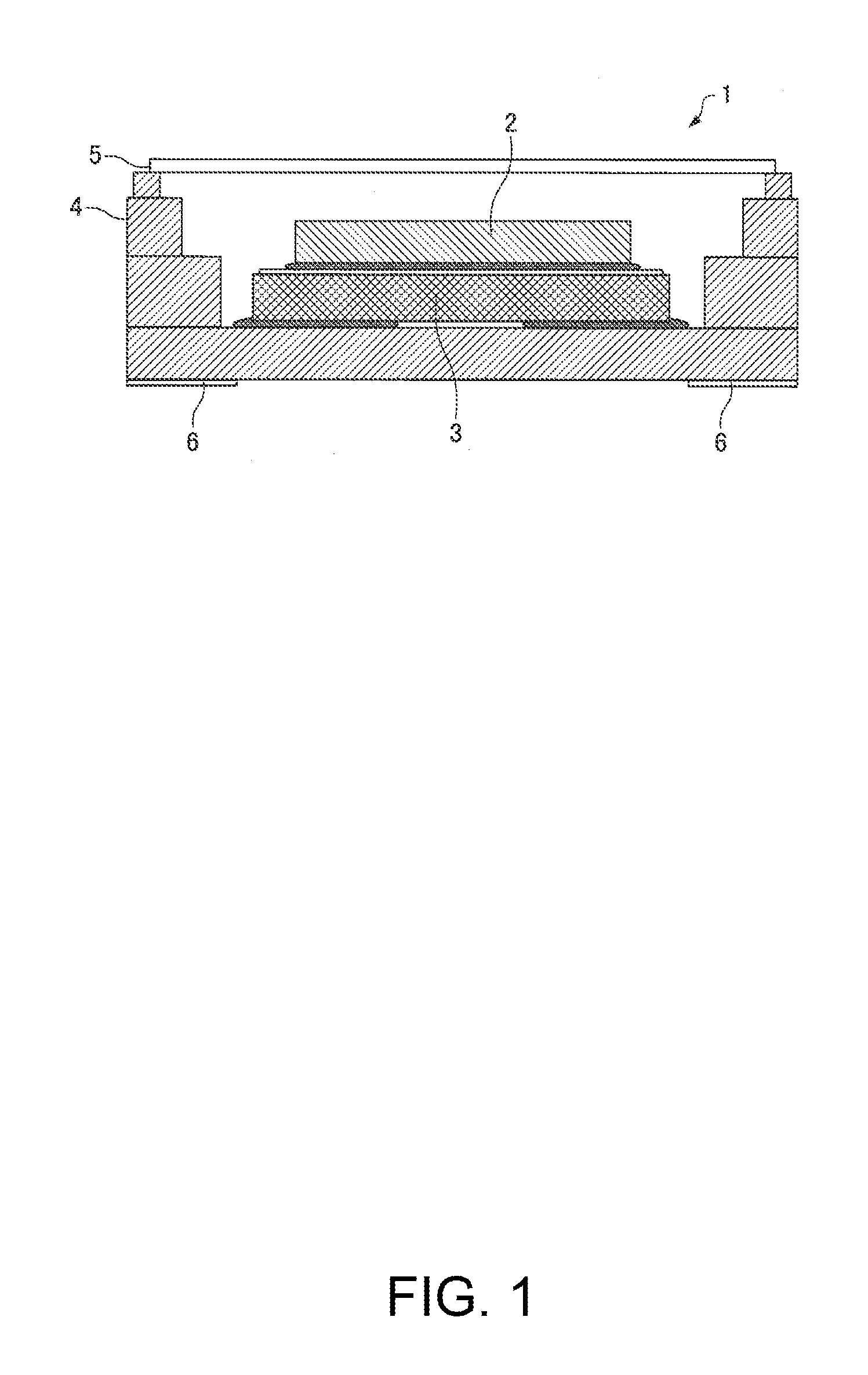
[0052]FIG. 1 is a diagram showing an example of a structure of an oscillator according to a first embodiment, and is a cross-sectional view of the oscillator. As shown in FIG. 1, the oscillator 1 according to the first embodiment is configured including an integrated circuit (IC) 2, a vibrator 3, a package 4, a lid 5, and external terminals (external electrodes) 6.

[0053]The package 4 houses the integrated circuit (IC) 2 and the vibrator 3 in the same space. Specifically, the package 4 is provided with a recessed part, and the recessed part is covered with the lid 5 to thereby house the integrated circuit (IC) 2 and the vibrator 3. On the surfaces of the inside or the recessed part of the package 4, there is disposed the wiring not shown for electrically connecting two terminals of the integrated circuit (IC) 2 and two terminals of the vibrator 3 respectively to each other. Further, on the surfaces of the inside or the recessed part of ...

second embodiment

1-2. Second Embodiment

Configuration of Oscillator

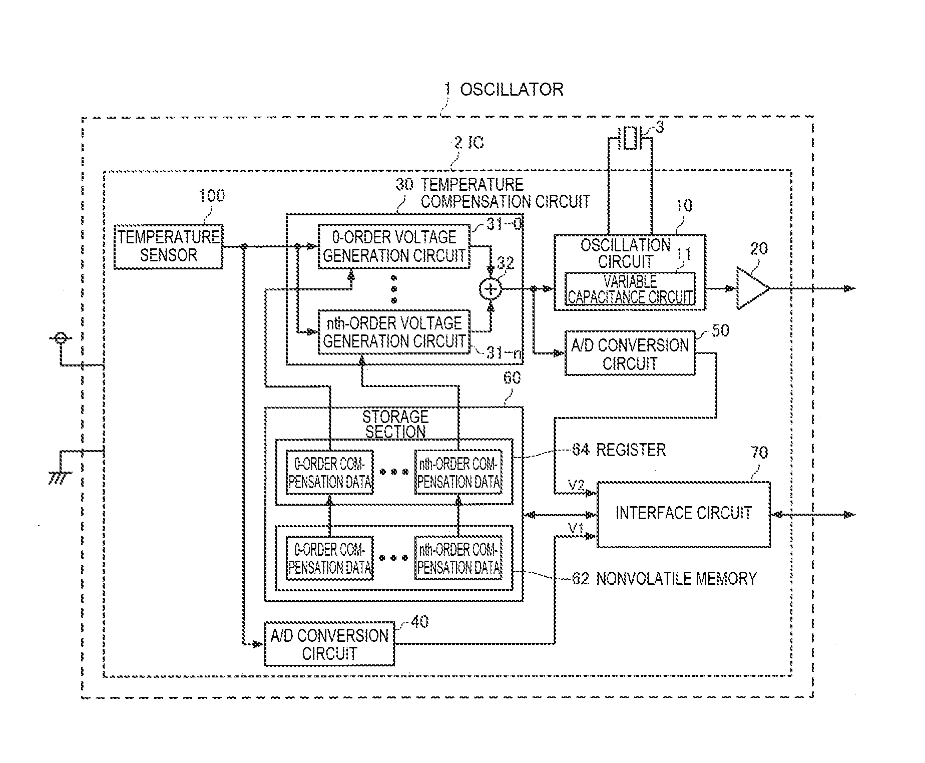
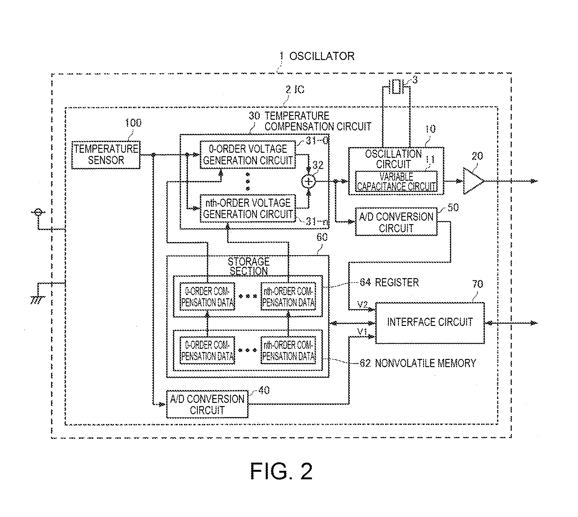
[0098]Since the structure of an oscillator according to a second embodiment can substantially be the same as shown in FIG. 1, the illustration and the explanation thereof will be omitted. FIG. 9 is a functional block diagram of the oscillator according to the second embodiment. In FIG. 9, the constituents substantially the same as those in FIG. 2 are denoted by the same reference symbols, and the second embodiment will hereinafter be described with a focus on different contents from the first embodiment, and the description redundant to the first embodiment will be omitted.

[0099]In the second embodiment, similarly to the first embodiment, the integrated circuit (IC) 2 is configured including the oscillation circuit 10, the output circuit 20, the temperature compensation circuit 30, the A / D conversion circuit 40, the A / D conversion circuit 50, the storage section 60, the interface circuit 70, and the temperature sensor 100, and further...

third embodiment

1-3. Third Embodiment

Configuration of Oscillator

[0131]FIG. 12 is a diagram showing an example of a structure of an oscillator according to a third embodiment, and is a cross-sectional view of the oscillator. As shown in FIG. 12, the oscillator 1 according to the third embodiment is configured including the integrated circuit (IC) 2, the vibrator 3, the package 4, external terminals (external electrodes) 6, a heat generating element 7, and a temperature sensor 8.

[0132]The package 4 is constituted by a case 4a and a base 4b bonded to each other.

[0133]In the internal space of the package 4, there is disposed a component mounting board 4c so as to be opposed to the base 4b, and an oven 9 is mounted on the upper surface of the component mounting board 4c. Further, on a lower surface of the component mounting board 4c, there is mounted the integrated circuit (IC) 2.

[0134]The vibrator 3 and the temperature sensor 8 are mounted on an upper surface of a component mounting board 9a, and the h...


PUM


Abstract

An electronic device includes a drive section, a detection signal output section adapted to generate a first analog signal having a value varying in accordance with a physical quantity, and a control section adapted to generate a second analog signal controlled based on the first analog signal, and adapted to control a drive state of the drive section, at least the detection signal output section and the control section are provided to a substrate, and a first digital signal obtained by digitalizing the first analog signal and a second digital signal obtained by digitalizing the second analog signal can be output from the substrate.

Description

BACKGROUND[0001]1. Technical Field[0002]The present invention relates to an electronic device, a method of manufacturing an electronic device, an electronic apparatus, and a moving object.[0003]2. Related Art[0004]In JP-A-2002-204127 (Document 1), there is disclosed an adjustment device for adjusting a temperature compensated crystal oscillator (TCXO) constituted by an oscillation circuit using a crystal vibrator and a variable capacitance element, a temperature sensor, an A / D converter, a D / A converter, a CPU, a memory, and an integration circuit. The adjustment device described in Document 1 obtains control voltage data of the variable capacitance element using the frequency deviation-temperature characteristic of the crystal vibrator itself and an output signal of the temperature sensor output from the temperature compensated crystal oscillator, and then stores the control voltage data in the memory so as to correspond to the ambient temperature and the frequency deviation of the...

Claims


Application Information

Patent Timeline
Patent Type & Authority Applications(United States)
IPC IPC(8): H03L1/04
CPCH03L1/04H03B5/04H03L1/025H03L1/028H03L7/099H03L1/026H03L1/02
Inventor TERASAWA, KATSUYOSHI
Owner SEIKO EPSON CORP
Learn More